Continue to Site

Welcome to EDAboard.com

Welcome to our site! EDAboard.com is an international Electronics Discussion Forum focused on EDA software, circuits, schematics, books, theory, papers, asic, pld, 8051, DSP, Network, RF, Analog Design, PCB, Service Manuals... and a whole lot more! To participate you need to register. Registration is free. Click here to register now.

Impedances in ATSC tuners and antennas for them...

Status
Not open for further replies.

Externet

Advanced Member level 2
Joined
Jan 29, 2004
Messages
579
Helped
28
Reputation
58
Reaction score
29
Trophy points
1,308
Location
Mideast US
Activity points
5,664
Hi all.
I find the subject way off reality.
Impedances are tied to a frequency, and rating tuners as for 75Ω, makes no sense in a span from ~50MHz to ~800MHz. It may hit 75Ω at a few places, but in general, it is a lie.

Same with television antennas. Rated 75Ω for similar span. That cannot be right. But has been like that and accepted since day one.
I suspect modern tuners are much higher impedance, but data sheets are very hidden or just unpublished as even the manufacturers may not know the exact specifications, or conflict with 'nominal standards'. Being much higher impedance tuner inputs, nears irrelevancy. A low impedance source antenna can feed a high impedance tuner very well, no power transfer matching needed. But the reception voltage would increase with proper matching and improve sensitivity to marginal signals.

But still the industry uses 75Ω cables and antennas.

What is your opinion or approach to design a plain TV antenna and feed line to really perform when feeding modern tuners ? -Thinking out of the 75Ω box-
Is there any pertinent study about receiving the best optimal signal in what normally is trial and error and guessing ?

Seen 'super' and expensive TV antennas, surpassed in performance by a properly positioned piece of coat hanger, and sometimes by an unterminated piece of RG59 or RG whatever (behave the same!) tossed behind a piece of furniture and fixed there at the best position and shape.
 

Most broadband tuners are fairly random impedance wise, AND IT DOES NOT MATTER....

Even if the thing is 150R at some point that is still only a 2:1 VSWR which would be something of an issue in a transmitter but amounts to a loss of a small fraction of a dB in a recever (and lowest overall noise figure may not occur at best power match anyway).

Folks quote 75 ohms because you have to quote something and it is a standard, but 75, 50 whatever is pretty much a non issue for a telly.

For good antenna performace you follow the same rules you do for any aerial, make it only as wideband as it has to be, somehting 10MHz wide at UHF is always going to be better then something 400MHz wide, keep the loss resistance small and the radiation resistance sane, and use to polar pattern to your advantage, then use low loss feedline with any gain at the head end only being sufficient to make up the line losses (Front end overload again).

Use a tuned filter ahead of the RF stage if using a high gain aerial (Probably been more trouble caused by overloading the front end then has been solved by additional gain).

Seriously, telly tuners are a cheap as they can be made, you could do much better but why bother when modern telly is digital and the proportion of users in weak signal areas that would need a better tuner hardly constitutes a market, once you have sufficient signal a better tuner will not significantly lower the BER.

73, Dan.
 

A well designed Log Periodic antenna can provide a fair VSWR at the 75 ohms impedance port, for a frequency range from 50 MHz to 800 MHz.
 

A well designed Log Periodic antenna can provide a fair VSWR at the 75 ohms impedance port, for a frequency range from 50 MHz to 800 MHz.

Can you please locate a frequency versus impedance plot for such well designed antenna, and the same for a modern ASC television tuner ?
The point is the questionable 75Ω of that 'well designed' antenna is not what modern tuners want.
And a log periodic may not be either what is desired for omnidirectional reception.

Yesterday, I replaced a collapsable plain rod antenna that has had marginal 515MHz reception for years at all thinkable positions and extended lenghts with a 60cm. circumference loop.
The reception does not fade away any more with vehicles passing by nor with people moving nearby. It is supposed to be ~280Ω impedance
 

RL=7-10dB is an acceptable rates for a industry TV Tuners.
No-one hopes more than this because of very wideband.
 

If you want to avoid interference of nearby signals that are co-channel such as itself off cars or Ricean Fading, you want a more directional antenna.

If you want to attenuate nearby tower signals to reach a city >200 km away then you want a high gain antenna pointing on the distant city, anything can get the local signals.

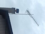
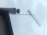
:smile: This is what I use at home to attenuate CN tower in Toronto to prevent modulated saturation of front end and pick up a dozen more HD channels in Buffalo. UHF Bowtie , gain=16 dB IMG_1130.JPG
 

Attachments

  • 08D3F3CF-B16C-4907-AAC9-B4EB59B6B962.JPG
    08D3F3CF-B16C-4907-AAC9-B4EB59B6B962.JPG
    612.7 KB · Views: 105

Thanks. This is getting off topic. It is not about directionality, gain, interference, selectivity.

It is about how to design an antenna that will provide the optimal matching a modern TV tuner wants to see.

I believe the true tuner specifications are needed to start. [A plot frequency/impedance] Then, select/calculate/build an antenna out of the sadly accepted and wrong industry nominal for 75Ω --Am I wrong in this rationale ?

The few tuner data sheets able to find show nothing, as one attached at the bottom, or show "Nominal" impedance.

And portion of an evaluation ----> https://s588.photobucket.com/user/Innernet/media/Screenshot-TVantennapdf.png.html?sort=6&o=40
 

Attachments

  • Screenshot from 2014-08-16 14:41:53.png
    Screenshot from 2014-08-16 14:41:53.png
    124.7 KB · Views: 93

Status
Not open for further replies.

Part and Inventory Search

Welcome to EDABoard.com

Sponsor

Back
Top