Continue to Site

Welcome to EDAboard.com

Welcome to our site! EDAboard.com is an international Electronics Discussion Forum focused on EDA software, circuits, schematics, books, theory, papers, asic, pld, 8051, DSP, Network, RF, Analog Design, PCB, Service Manuals... and a whole lot more! To participate you need to register. Registration is free. Click here to register now.

impedance of transducer and receiver

Status
Not open for further replies.

jimmykk

Full Member level 3
Joined
Oct 2, 2014
Messages
158
Helped
0
Reputation
0
Reaction score
1
Trophy points
1,298
Activity points
2,863
Hi

I need some help regarding some basic thing. I have a transmitter which is connected to
a: transducer that has 200ohm resistance at resonance frequency 50khz.
b: receiver that has a coil in series which gives 2.5kohm resistance at 50khz.

My question is when the transmitter transmits, what happens and where does the maximum amount of voltage flows..... to transducer or to receiver? And when a signal is received then what happens.
pLEASE explain.
 

Your circuit description is rather unclear. You should show a schematic to allow a serious discussion.

Voltage doesn't "flow". The receiver voltage of an ultrasonic transmission system will be lower by several orders of magnitude than the transmitter voltage, despite of circuit details.
 

The transmitting transducer is probably series resonant so that its current is high but its voltage is low.
The receiving coil should be tuned and since its resistance is high then it has many turns of wire and is probably parallel resonant so that its current is low and its voltage is as high as it can be depending on its load resistance and distance.
 

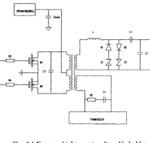
Here is my circuit:-

Captu.PNG

and how will it affect the bandwidth of the system?
 

I guess that the receiver LC circuit is tuned to operate the transducer in series resonance.

For an exact calculation, all circuit parameters and the transducer impedance curve must be known.
 

yeah it is a piezoelectric transducer.
on the left is a pair of transistors for transmission, in center is the transformer, upper right is the receiver and lower right is the transducer.
 

I assume that you transmit a signal, wait for the resonance of the transducer to die down then receive an echo of the signal on the same transducer.
Then the receiver circuit is receiving a very low signal level when receiving the echo.
Then the receiver circuit is receiving a whopping high signal level when you are transmitting.
 
Last edited:

exactly.....My question is:
How the resonance circuit protects receiver during transmission and
Why most of the voltage goes through transducer and not to receiver while transmitting because as far as i know the load resistance should be greater than the source resistance for maximum voltage ttransfer. And here receiver has the maximum load.
 

The receiving circuit uses those back-to-back avalanche diodes to clamp the input voltage when the circuit is transmitting.
The transmitting circuit must have an impedance that is much lower than the 200 ohm resistance of the transmitting transducer. Then most of its voltage goes to the transducer for maximum output power.
 

Status
Not open for further replies.

Part and Inventory Search

Welcome to EDABoard.com

Sponsor

Back
Top