Continue to Site

Welcome to EDAboard.com

Welcome to our site! EDAboard.com is an international Electronics Discussion Forum focused on EDA software, circuits, schematics, books, theory, papers, asic, pld, 8051, DSP, Network, RF, Analog Design, PCB, Service Manuals... and a whole lot more! To participate you need to register. Registration is free. Click here to register now.

Impedance measurement scheme

Status
Not open for further replies.

anushaas

Member level 5
Joined
Jan 4, 2011
Messages
84
Helped
0
Reputation
0
Reaction score
0
Trophy points
1,286
Activity points
1,979
I need to measure impedance over a range of 1 Ohm to 3 MOhm. The impedance variation happens over a frequency range of 2 MHz to DC (ie. impedance is 3 MOhm at DC and 1 Ohm at 2 MHz).Can any one suggest a suitable measurement scheme for measurement?

I thought about a constant current excitation scheme(ie.maintaining a constant current flow through the impedance and measure the voltage across it.The impedance will be the ratio of voltage and current).But for my pplication the current cannot be less than some 75uA. This however, makes the voltage across 3MOhm equal to 225V which is too high.

The constant voltage excitation,similarly, might cause a very low or high current flow at the extremes.

Can some one help me with a possible scheme of measurement which can incorporate all the constraints?
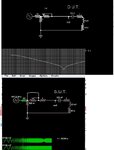
 

can you not use a function generator (modern ones have a frequency sweep function) add a small series resistor, record voltage across the series resistor as the frequency sweeps and you have your impedance.
 

The impedance and frequency range (apart from the DC capability) would be covered by good LCR meters like Agilent E4980. You could consider to use a similar measurement principle (auto balance bridge).
 

circa 70's-80's , I used to measure input impedance by using the scope X sweep out on the back to drive an FM input sweep generator then examine the envelope ratio on the scope for a linear frequency response.

I got fancier by using X sweep out into Channel 1 then use CH1 Out on back of scope to FM input on Sig Gen so I could adjust the sweep ramp voltage level and offset to select my start / Stop frequency.

Then I used sweep Ch1 Signal input to Gnd with vertical adjust to choose the range of Voltage and range of frequency for start and stop, then change probe input back to DC signal to use the same levels as the DC out using the scope to set the FM Gen frequency. Sounds complicated but it was easy for me.

I dont think DSO's have this feature now. I used this on all HP and Tek scopes. It was a great feature.

You can then add a series R box or 1M pot to scale your transfer function from the Generator 50 Ohms to 1 MOhm to get your impedance ratio where 50% Vout means Zin matches your source impedance.

- - - Updated - - -

To sweep over such a wide dynamic range of impedances would be impractical on a scope unless you chose to switch source impedances.

Is this for a production test or design verification?

Using a signal source at different frequencies, one can measure impedance by phase shift and amplitude reduction but you need a log scale in dB and log f like a spectrum analyzer to make that work. Or a Bode plot device. or an impedance analyzer.

But for design verification, a simple sig. gen and series R and scope will do.
Z in.jpg

FWIW, RLC meters use a constant current source sine wave at fixed frequencies to measure V as Z in amplitude and phase obviously with auto scaling on current, but limited in V and I to practical levels.
 

dont think DSO's have this feature now. I used this on all HP and Tek scopes. It was a great feature.
They don't. But there is nothing stopping you making a ramp generator and feeding it into the external X input of a DSO!

Brian.
 

Status
Not open for further replies.

Part and Inventory Search

Welcome to EDABoard.com

Sponsor

Back
Top