Continue to Site

Welcome to EDAboard.com

Welcome to our site! EDAboard.com is an international Electronics Discussion Forum focused on EDA software, circuits, schematics, books, theory, papers, asic, pld, 8051, DSP, Network, RF, Analog Design, PCB, Service Manuals... and a whole lot more! To participate you need to register. Registration is free. Click here to register now.

Impedance matching on RF stages of vlf RX

Status
Not open for further replies.

neazoi

Advanced Member level 6
Joined
Jan 5, 2008
Messages
4,122
Helped
13
Reputation
26
Reaction score
15
Trophy points
1,318
Location
Greece
Activity points
36,951
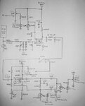
Hello I have designed this VLF RX for whistlers reception. I have joined together two projects (two fets) from different circuits.
The output volume of the first fet is ok for my ssd recorder.
when I connect the second stage fet, the output volume goes down very much. Being a twin notch filter, the second stage, it works ok, but it attenuated much the total volume as well. I would expect the total volume to be at least equal to that of the first stage alone, so that is why I believe there is an impedance mismatching somewhere.
I believe this is an impedance matching problem, either on the input of the first stage or in its output.

I have no idea what is the output impedance of the first stage or the input impedance of the second stage, and I do not know how to correct this.
Any suggestions???
 

Attachments

  • vlf.jpg
    vlf.jpg
    75.5 KB · Views: 127

My suggestion would be to draw this stage in ADS (advance design system) , check S22 of first stage over your frequency range, take impedance value at center of your frequency band, note it down..
Now draw the second stage and check S11 now, note center value this would be the input impedance of second stage, write it down.
Now through "Smith Chart Matching" utility of ADS, you can have your matching network, which actually transforms your output impedance of first stage to the input stage of the second stage..
But brother you need to first study about matching basics..

I hope someone has a better solution :)

Yes of course, but this requires ADS (very expensive) and knowledge of how to use it. Very accurate matching is not needed here. If only I could define the components (probably resistors) that affect impedance, I could replace them with potentiometers and find the best matching values.
any suggestions?
 

Hmmm ....then hope someone will have us both in finding solution :)
Don't you think if you replace your 100pf capacitors at first stage output with variable capacitor, and note your output by varying capacitance would do some good !!!!
 
  • Like
Reactions: neazoi

    neazoi

    Points: 2
    Helpful Answer Positive Rating
Hmmm ....then hope someone will have us both in finding solution :)
Don't you think if you replace your 100pf capacitors at first stage output with variable capacitor, and note your output by varying capacitance would do some good !!!!
no, the first stage is self biased, whereas the second stage is voltage divider biased. I think I will have to alter the bias resistors accordingly in the second stage, but I am not sure if this will help.

I believe I have to reduce this 1mohm resistor at the second stage G2. This will increase the voltage on G2 and increase the gain of this stage.
 
Last edited:

I have found the problem. it was the drain and source resistors of the second stage. maybe the transistor was starving. when I changed them to similar values like the first stage resistors, it worked loudly again.
Changing the gate resistor 1M, was not good.

BTW, how should I measure the current flowing through each fet? Is it enough to measure the voltage drop on the source resistor? what about the drain one?
 
  • Like
Reactions: Ow@i$

    Ow@i$

    Points: 2
    Helpful Answer Positive Rating
Status
Not open for further replies.

Similar threads

Part and Inventory Search

Welcome to EDABoard.com

Sponsor

Back
Top