Continue to Site

Welcome to EDAboard.com

Welcome to our site! EDAboard.com is an international Electronics Discussion Forum focused on EDA software, circuits, schematics, books, theory, papers, asic, pld, 8051, DSP, Network, RF, Analog Design, PCB, Service Manuals... and a whole lot more! To participate you need to register. Registration is free. Click here to register now.

Impedance matching. How to shrink the contour of the S11 on smith chart?

Status
Not open for further replies.

shmily0447

Advanced Member level 4
Joined
Apr 5, 2010
Messages
113
Helped
30
Reputation
60
Reaction score
19
Trophy points
1,298
Activity points
2,010
Hi guys,

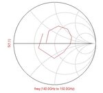
I have a trouble in matching the circuit. Can anyone kindly sugggest what I should do? Attached is the rectangular plot of the S11 and the S11 contour on smith chart.

Can anyone suggest that how I can shrink the contour of the S11 into the VSWR=2 circle in smith chart for a good matching?

It tortures me very much those days.
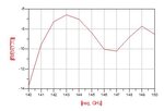
S11_Rectangular.JPGS11_SmithChart.JPG
 

How does the curve look if you adjust the matching circuit for S11=0 at center frequency?
 

How does the curve look if you adjust the matching circuit for S11=0 at center frequency?

Hi,

When I adjust the matching circuit, the S11 circle moves. But the contour of the S11 circle does not shrink. Any suggestions?
 

Can you show the load impedance curve?

Maybe the problem is resonant load (e.g. antenna with insufficient bandwidth). In this case it's probably not possible to achieve a better matching. Too much delay between load and matching network can be a problem as well.
 
load.JPG
Can you show the load impedance curve?

Maybe the problem is resonant load (e.g. antenna with insufficient bandwidth). In this case it's probably not possible to achieve a better matching. Too much delay between load and matching network can be a problem as well.

Hi FvM,

The load impedance is shown attached. It resonates at 145 GHz indeed.

Since I just need 10 GHz matching band from 140-150 GHz, or 7% bandwidth. Is it possible to achieve 7% impedance bandwidth with a resonant antenna?

- - - Updated - - -

Hi FvM,

Can you pls suggest why too much delay between the load and the matching network can cause the problem of limited bandwidth?

Tks.
 

My intuitive understanding is that you can't increase the antenna bandwidth with a lossless matching circuit.

- - - Updated - - -

And to refer to the other problem, one way to generate a resonant structure would be to connect a fairly wide band antenna through a mismatched transmission line of about 7 wavelengths.
 
Antenna impedance varies too much with frequency , therefore matching circuit cannot match these impedances.
You should use multiple stage ( for wideband) impedance matching circuit.
 
My intuitive understanding is that you can't increase the antenna bandwidth with a lossless matching circuit.

- - - Updated - - -

And to refer to the other problem, one way to generate a resonant structure would be to connect a fairly wide band antenna through a mismatched transmission line of about 7 wavelengths.

Hi FvM,

Thanks for the suggestion.

To increase the antenna's bandwidth with a lossy matching circuit, the gain could be decreased. Any idea about how to match the antenna while maintaining the gain at the same time.

I can not quite understand 'And to refer to the other problem, one way to generate a resonant structure would be to connect a fairly wide band antenna through a mismatched transmission line of about 7 wavelengths.' Could you please share more details?

- - - Updated - - -

Hi BigBoss,

Thanks for the suggestion.

Can you share more detailed information about the multi-stage impedance matching network? I mean, how I should design it, how it is supposed to look like?
 

I can not quite understand
I think the description is quite clear. As an example, have a 25 ohm antenna connected through a 50 ohm transmission line 7 wavelength long (e.g. 50 ps at 145 GHz), then try to match it to 50 ohms at the other end of the tranmission line.

Instead of making us guess, why don't you show the discussed structure?

Hi FvM,

Thanks for the reply. Unfortunately, I am not allowed to share the structure of the antenna.

Actually, it is an array. Each element matches well, meaning that they match well to a 50 Ohm load. But the feeding network seems too long compared with the guided wavelength. Instead of shorten the feeding network, is there any solutions for a good matching?

- - - Updated - - -

I think the description is quite clear. As an example, have a 25 ohm antenna connected through a 50 ohm transmission line 7 wavelength long (e.g. 50 ps at 145 GHz), then try to match it to 50 ohms at the other end of the tranmission line.

Instead of making us guess, why don't you show the discussed structure?

Moreover, for a 50 Ohm antenna, through a 50 Ohm transmission line, 7 wavelength long. The matching should still not be difficult. It is similar with my case. But unfortunately, I got terrible matching when a 50 Ohm antenna going through a very long 50 Ohm transmission line. .....
 

But unfortunately, I got terrible matching when a 50 Ohm antenna going through a very long 50 Ohm transmission line.
Something must be obviously wrong. Either the antenna is not 50 ohms, or it has already small bandwidth without the transmission line.

I claim that it's not possible to increase the antenna bandwitdh with a lossless network in either case. Please correct me if I'm wrong (by showing a respective example).

Thanks for the information. I will check it.
 

I think the description is quite clear. As an example, have a 25 ohm antenna connected through a 50 ohm transmission line 7 wavelength long (e.g. 50 ps at 145 GHz), then try to match it to 50 ohms at the other end of the tranmission line.

Instead of making us guess, why don't you show the discussed structure?

I agree, it looks like a well matched antenna with a length of transmission line between it and the network analyzer, where the transmission line is not the same as the antenna's impedance. Did you take the antenna S11 data RIGHT AT the antenna terminals??

It looks like it is either a 30 ohm or 90 ohm antenna
 

Status
Not open for further replies.

Similar threads

Part and Inventory Search

Welcome to EDABoard.com

Sponsor

Back
Top