kela3kela
Full Member level 4

- Joined
- Apr 30, 2009
- Messages
- 191
- Helped
- 5
- Reputation
- 10
- Reaction score
- 5
- Trophy points
- 1,298
- Activity points
- 2,502
I am simulating a paper of 2.45 GHz rectenna using ADS. The circuit diagram given in paper and made by myself in ADS are shown below;


I wanted to ask the following:
1. Firstly, is my circuit correctly implemented?
2. How did impedance matching occurred via ADS matching tool? I mean what parameters were selected in the tool? i.e. load value, parallel load etc...
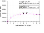
3. How to plot the output power vs R1 as shown in paper below;

PS. Reference paper attached.
Awaiting replies..
Regards


I wanted to ask the following:
1. Firstly, is my circuit correctly implemented?
2. How did impedance matching occurred via ADS matching tool? I mean what parameters were selected in the tool? i.e. load value, parallel load etc...
3. How to plot the output power vs R1 as shown in paper below;

PS. Reference paper attached.
Awaiting replies..
Regards

