ZackDillon
Newbie level 4
- Joined
- Jul 24, 2016
- Messages
- 5
- Helped
- 0
- Reputation
- 0
- Reaction score
- 0
- Trophy points
- 1
- Location
- Ann Arbor Michigan
- Activity points
- 58
Hello!
Let me start by saying I'm not experienced in the world of electronics. I know just enough to be dangerous.
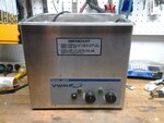
Some time ago I bought a used, not working 40KHz ultrasonic cleaner for next to nothing (1st picture) The generator PCB inside the unit is made by Crest. I replaced all the components that were obviously burned up (3 IC's and about 7 Transistors) . To make a long and irritating story short, it fried immediately when I put power to it. I would like to revisit fixing the original generator in the future (with a lot of help from you folks).
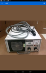
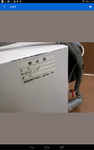
In the mean time I've (on a whim) purchased a used generator on eBay and I'm now awaiting it's arrival. See pics 2, 3 and 4.
I have searched the internet hi and low for ANY information on this generator and have come up with nothing.
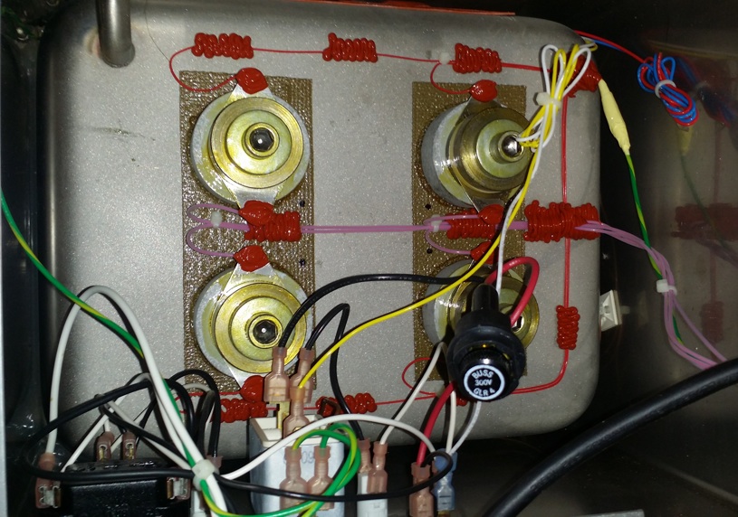
My plan\dream is to use this generator to drive the tank I have. I've removed the dead PCB and left the wiring that controls the heater for the tank. The tank has 4, 40KHz transducers (picture 4)with separate leads and a common ground wire.
I know I can destroy my new (to me) generator by running it without a load, or by wiring it to the transducers incorrectly.
My questions are, is anyone familiar with this generator and could shed some light on its specs? I'm pretty sure it's powerful enough to fry my transducers if it were run at full power.
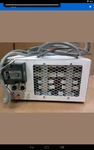
Does anyone recognize the round 3 prong plug? I assume it drives the tank. And how should I test those leads to determine which wire (s) go where.
Does anyone think the white 4 pronk plugs on the back of the generator are alternative power out plugs?
Assuming I get this rig working how do I "tune" the generator to the tank transducers?
My hope is to be ready to wire it to my tank correctly when it arrives next week.
THANK YOU in advance for your time and input.

Let me start by saying I'm not experienced in the world of electronics. I know just enough to be dangerous.
Some time ago I bought a used, not working 40KHz ultrasonic cleaner for next to nothing (1st picture) The generator PCB inside the unit is made by Crest. I replaced all the components that were obviously burned up (3 IC's and about 7 Transistors) . To make a long and irritating story short, it fried immediately when I put power to it. I would like to revisit fixing the original generator in the future (with a lot of help from you folks).
In the mean time I've (on a whim) purchased a used generator on eBay and I'm now awaiting it's arrival. See pics 2, 3 and 4.
I have searched the internet hi and low for ANY information on this generator and have come up with nothing.
My plan\dream is to use this generator to drive the tank I have. I've removed the dead PCB and left the wiring that controls the heater for the tank. The tank has 4, 40KHz transducers (picture 4)with separate leads and a common ground wire.
I know I can destroy my new (to me) generator by running it without a load, or by wiring it to the transducers incorrectly.
My questions are, is anyone familiar with this generator and could shed some light on its specs? I'm pretty sure it's powerful enough to fry my transducers if it were run at full power.
Does anyone recognize the round 3 prong plug? I assume it drives the tank. And how should I test those leads to determine which wire (s) go where.
Does anyone think the white 4 pronk plugs on the back of the generator are alternative power out plugs?
Assuming I get this rig working how do I "tune" the generator to the tank transducers?
My hope is to be ready to wire it to my tank correctly when it arrives next week.
THANK YOU in advance for your time and input.
Attachments
Last edited by a moderator: