dpaul
Advanced Member level 5
Hello,
I have a working system in which a Xilinx AXI IIC IP (v1.02a) acts as the master transmitter and it is connected to an IIC slave (I2C Slave by Steve Fielding @ OpenCores). These two IPs belong to a uP system, so I basically write a C-code to test the IIC transactions (the uP generates AXI bus transactions which can R/W the registers of the Xilinx AXI IIC IP and as per command written in the control reg., IIC transactions are to be generated).
The problem is, I always see a NACK after the AXI_IIC master tries to put the slave device address on to the SDA bus; even though there is data queued in the tx_fifo of the IIC master. After that NACK and STOP condition, there is no IIC activity on SDA and SCL.
Why is this happening?
I have changed the device address in the file i2cSlave_define.v and everything which is supposed to be done as per the spec of the iic slave IP to make it workable. I am using the 'Dynamic Controller flow logic' of the AXI IIC master IP (Xilinx spec), and accordingly have written the C-code.
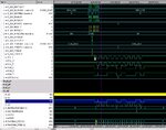
Attached below is the screenshot of my simulation.

One can see that on the 9th SCL pulse, SDA is HIGH which means a NACK as per Philips UM10204 spec. Now as per Pg10 of this spec-
There are five conditions that lead to the generation of a NACK:
1. No receiver is present on the bus with the transmitted address so there is no device to respond with an acknowledge.
2. The receiver is unable to receive or transmit because it is performing some real-time function and is not ready to start communication with the master.
3. During the transfer, the receiver gets data or commands that it does not understand.
4. During the transfer, the receiver cannot receive any more data bytes.
5. A master-receiver must signal the end of the transfer to the slave transmitter.
<1>, <2> and <5> are ruled out. I do have this IIC slave IP connected and have configured it to be at address 0x34 (by changing the 'define' file). I also know that the slave is not doing anything in this time when the address is being transmitted. Scenario <5> is invalid as I have an AXI_IIC IP being the master transmitter.
Any ideas as to why this NACK is happening?
Thanks for you patience in reading through this!
I have a working system in which a Xilinx AXI IIC IP (v1.02a) acts as the master transmitter and it is connected to an IIC slave (I2C Slave by Steve Fielding @ OpenCores). These two IPs belong to a uP system, so I basically write a C-code to test the IIC transactions (the uP generates AXI bus transactions which can R/W the registers of the Xilinx AXI IIC IP and as per command written in the control reg., IIC transactions are to be generated).
The problem is, I always see a NACK after the AXI_IIC master tries to put the slave device address on to the SDA bus; even though there is data queued in the tx_fifo of the IIC master. After that NACK and STOP condition, there is no IIC activity on SDA and SCL.
Why is this happening?
I have changed the device address in the file i2cSlave_define.v and everything which is supposed to be done as per the spec of the iic slave IP to make it workable. I am using the 'Dynamic Controller flow logic' of the AXI IIC master IP (Xilinx spec), and accordingly have written the C-code.
Code:
int main()
{
//-------------------------------------
// Test AXI_IIC_S0 'Dynamic IIC access'
//-------------------------------------
// 0xc0 menas FIFOs are empty
printf("\n AXI_IIC_SR_S0 = %8x \n", AXI_IIC_SR_S0);

// Initialization
// --------------
RX_FIFO_PIRQ_S0 = 0x0f; // Set rx_fifo depth to max
AXI_IIC_CR_S0 = 0x2; // Reset the TX_FIFO (0000, 010)

// Enable the AXI IIC, remove the TX_FIFO reset, disable the general call (0000, 001)
AXI_IIC_CR_S0 = 0x1;

// Write 4 bytes to an IIC Slave @ 0x34
// -------------------------------------
//AXI_IIC_SR_S0; // Chk all FIFOs empty and bus not busy

// Read the CR
AXI_IIC_CR_S0;

// Set start bit, device address and write access
AXI_IIC_TX_FIFO_S0 = 0x134; // Address of the slave device
// *** You can see this 0x34, device address, or 00110100 being tx. on the SDA

AXI_IIC_TX_FIFO_S0 = 0x00; // Register address of the slave for data transfer
AXI_IIC_TX_FIFO_S0 = 0x89; // Byte 1
AXI_IIC_TX_FIFO_S0 = 0xab; // Byte 2
AXI_IIC_TX_FIFO_S0 = 0xcd; // Byte 3
AXI_IIC_TX_FIFO_S0 = 0x2ef; // Byte4 and STOP bit

printf ("\n IIC_s0 operation done, begin IIC_s1 operation!\n");

return 0;
}
Attached below is the screenshot of my simulation.

One can see that on the 9th SCL pulse, SDA is HIGH which means a NACK as per Philips UM10204 spec. Now as per Pg10 of this spec-
There are five conditions that lead to the generation of a NACK:
1. No receiver is present on the bus with the transmitted address so there is no device to respond with an acknowledge.
2. The receiver is unable to receive or transmit because it is performing some real-time function and is not ready to start communication with the master.
3. During the transfer, the receiver gets data or commands that it does not understand.
4. During the transfer, the receiver cannot receive any more data bytes.
5. A master-receiver must signal the end of the transfer to the slave transmitter.
<1>, <2> and <5> are ruled out. I do have this IIC slave IP connected and have configured it to be at address 0x34 (by changing the 'define' file). I also know that the slave is not doing anything in this time when the address is being transmitted. Scenario <5> is invalid as I have an AXI_IIC IP being the master transmitter.
Any ideas as to why this NACK is happening?
Thanks for you patience in reading through this!