Continue to Site

Welcome to EDAboard.com

Welcome to our site! EDAboard.com is an international Electronics Discussion Forum focused on EDA software, circuits, schematics, books, theory, papers, asic, pld, 8051, DSP, Network, RF, Analog Design, PCB, Service Manuals... and a whole lot more! To participate you need to register. Registration is free. Click here to register now.

IGBT DC-DC converter with IGBT

Status
Not open for further replies.

kornjace

Newbie level 3
Joined
Jan 18, 2011
Messages
4
Helped
0
Reputation
0
Reaction score
0
Trophy points
1,281
Activity points
1,324
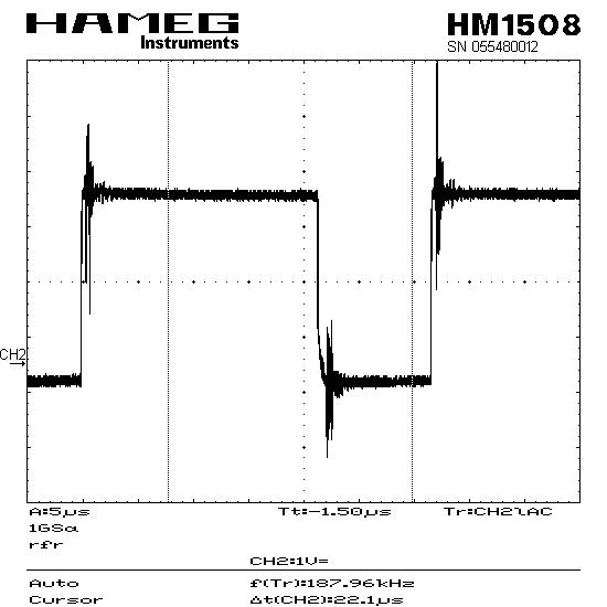
Hi, I' ve constructed an DC-DC converter with IRG4PC30KD. I'm driving it with a PWM from a pic at 20 kHz. (attacment 1) what I tried to achive was do dim a 12V DC lamp. now, on the outside, it's seem all fine, becouse i can dim the lamp from 1 - 99% duty cycle, and the dimming is very linear. but, when i'm mesuring the voltage on the lamp with an osciloscope, i can see a peak of voltage (attacment 2). this peak consurnes me, becouse the final goal is to construct an AC-AC converter, to dim a 2 kW AC reflector. powered with 220V AC. there these peaks may occur much more stronger and fry the circuit.

so my first question is, how can I get rid of those peaks?

and the second thing, if you can give me a tip how to construct an AC-AC converter. I know that i have to use the IR2110. ir2117 test.JPGView attachment voltage on lamp.BMP
 

Those peaks are coupled from the switching transients of your IGBT and diode. You can get them off your load by additional filtering (just a good LC filter), but when you probe your circuit you will probably see it a little bit no matter what, since it will couple via EMI. If that's the case then it's probably nothing to worry about, but if you really want to get rid of it you'll need a snubber circuit somewhere.
 

so, maybe just a good filter will do just fine. now, the question i have, is where to put it in the circuit?

here I have another image of the PWM signal after i connect it to my buck circuit.
the output from the pic is very stable, without that peaks, but after I connect it, the peaks are there.


I've connected an optocoupler between the output of the pic and the input to the IR2117 drive. there souldn't be any peaks?
 

I should hunt for a link to something that tells you about scope probe measurements but for the moment if you are measuring using the ground lead that connects into the body of the probe then this might be the source of your problems. Basically it makes a nice 'loop aerial'. You can see in your picture that the PIC says 'switch!' and then there is a delay, through the opto then through the driver and then to 'wake up' the IGBT before it finally does and then you get your ringing 'splack' on the waveform.

Just behind the tip of your probe there should be a 'shiny' ground ring and if your probe is new and you have not lost them then it would have come with one or two coily bits of spring with an end bent out to extend to or past the tip. If you unplug the ground lead and slip one of those on then make the measurement with tip on the point you wish to look at and the springy thing poked onto a 'local' ground track then you should see a cleaner waveform.

If you have lost the springy things then you can make your own with a coiled bit of solid copper wire or try soldering a BNC on the measurement point and plug the probe directly into that.

Sorry for the poor description. I believe is might be called a 'short lead measurement'.

Genome.
 

A agree with Genomerics. With a reasonable circuit design and measurement setup, the shown spikes won't be seen with that high level across the load. Additional filtering may be required to keep EMI regulations though. But you'll observe more transients at the input side, where the current is discontinuous.

Apart from this, I wonder what you want to achieve. What do you mean with a 2 kW "reflector"? A spotlight? Ligthing applications are mostly controlled by a dimmer (triac/SCR switch with phase angle control). For a heater, full wave switching would be appropriate.
 

yes, that's exactly what i want to achieve, to dim a spotlight. I already have a dimmer with triac, but this technology is a bit old. now I want to make a dimmer using igbt. the final produsct would be probably more silent, a smaller coils will be used, so it would be also lighter. for example a triac dimmer on it's 70% output power makes a lot of noises. so that's my goal...

ok, today i've tried to replace the 12V lamp with 24V. still, the dimming is good, but the peaks of voltage on the lamp are now higher. I really hope that those are just from bad measurement, but I doubt it... anyway, if I want to place a filter in the circuit, where should I place it? any suggestions?

apart that, i have started to look at AC-AC converter. I also have the IR2110 driver, but still don't know how to connect it. i've looked at the application note of the driver, but that test circuit is just for DC, am I right?
 

this technology is a bit old. now I want to make a dimmer using igbt. the final produsct would be probably more silent, a smaller coils will be used, so it would be also lighter
There are reasons, why this old technology is still used. A 10 A choke isn't a large or heavy component. I fear, you'll have difficulties to achieve the same form factor with a high frequency chopper.
I really hope that those are just from bad measurement, but I doubt it
Remember my comment: With a reasonable circuit design and measurement setup, the shown spikes won't be seen with that high level. I mentioned two conditions. Genomerics has commented the measurement setup. Now about the other condition. We can say, that the 40 µF capacitor together with the inductor won't allow large spikes at the load. But firstly it depends on how the capacitor is connected. And secondly, by drawing the pulsed input current from the power supply without any bypass capacitor, you'll "contaminate" the enviroment with current transients of some 100 A/us. It's rather difficult to make an interference free measurement in the vicinity.

I'm curious how you want to setup the AC-AC converter.
 

I see what you mean. I'll try to make a better measuring setup, and i know that the circuit design is not perfect or without any problems.

The idea for an ac-ac converter comes from this article: **broken link removed**
on the 2. page, there is a shematics on how the ac converter should work. now the problem is how to realize that with the Ir2110. What do you think about this theory? I really appreciate your comments, and I'm very thankfull.
 

now the problem is how to realize that with the Ir2110
You need an opto or inductive coupled gate driver signal and a DC/DC converter in this case. Transformer coupled gate drive with a pulse shaper can work, too.
I don't know, if you actually need a buck-boost converter. The disadvantage is, that all energy must go through the inductor, in contrast to a buck or non-inverting boost converter, where the inductor only supplies an energy amount correspending to the voltage difference.

As another disadvantage, there are not less than 4 diode and 2 IGBT voltage drops carrying the full load current. So the efficiency will be considerably worse than a simple triac dimmer.
 
Last edited:

As FvM says, a conventional dimmer ckt is far more efficient than a switchmode AC/AC converter. AC/AC converters for industry are commonplace for providing more stable AC supplies to factories etc that need decent AC power. For powering low voltage lamps from the mains, simple switchmode solutions exist (the simplest using high freq AC as the output) but have higher cost and lower efficiency than a triac or dual SCR.

Having developed 3kW S/Mode AC/AC dimmers for controlling theatrical lighting units I can say there is a fair bit of work involved to get a properly compliant product (<5mA DC drawn from the mains, EMC compliance, etc).

Regards, Orson Cart
 
Last edited:
  • Like
Reactions: FvM

    FvM

    Points: 2
    Helpful Answer Positive Rating
Having developed 3kW S/Mode AC/AC dimmers for controlling theatrical lighting units I can say there is a fair bit of work involved to get a properly compliant product (<5mA DC drawn from the mains, EMC compliance, etc).
Thanks for mentioning state-of-the-art in this regard. Is this technique already frequently used in professional lighting today? How do you think about it's future potential?
 

The switchmode converters we have worked on for theatrical lighting users and makers are being made in the thousands and the use is quite widespread, the ones we developed could be run off a conventional SCR/TRIAC dimmer o/p also, as many theatres are already setup for this (in their wiring). Future potential is pretty high using low level RF to control the lamps from the dimmer panel and each lamp is plugged direct into the mains, awaiting commands from the dimmer panel. Each converter/lamp has a small pot on the outside so the max rms volts to the lamp can be set and not over-ridden by dimmer commands - especially useful for the 90VAC philips lamps in widespread use today in theatres.

Regards, Orson Cart
 
Last edited:

Status
Not open for further replies.

Similar threads

Part and Inventory Search

Welcome to EDABoard.com

Sponsor

Back
Top