Continue to Site

Welcome to EDAboard.com

Welcome to our site! EDAboard.com is an international Electronics Discussion Forum focused on EDA software, circuits, schematics, books, theory, papers, asic, pld, 8051, DSP, Network, RF, Analog Design, PCB, Service Manuals... and a whole lot more! To participate you need to register. Registration is free. Click here to register now.

IGBT based circuit Simulation with PSpice

Status
Not open for further replies.

atripathi

Advanced Member level 1
Joined
Dec 2, 2009
Messages
450
Helped
91
Reputation
182
Reaction score
88
Trophy points
1,318
Location
INDIA
Activity points
3,818
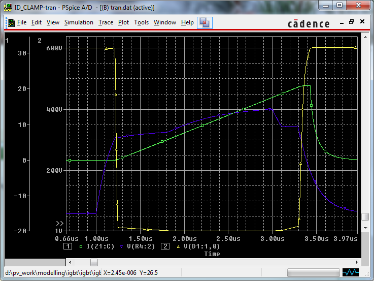
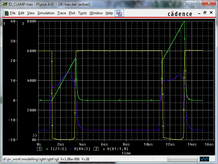
Has any one tried simulating IGBT with PSpice for accurate power loss and switching characteristics under HARD switching conditions?
How accurate the simulation results are?
 

Hey Dude!
Hi
What do you mean by accurate power loss?! approximately all of Pspice simulations are true if you know right way for simulation! What kind of circuit would you like to do simulation with pspice?
Best Regards
Goldsmith
 

Thanks. By "Accurate power Loss" I mean getting correct switching loss, mainly to include Tail current effect etc for IGBT in hard switching mode. My question is more on how good the IGBT models are?
 

Looking at the PSPICE IGBT equations and model parameters, I don't see, how tail current should be represented. Models can be verified in a test bench. Did you try?

Presuming that the standard IGBT models don't implement tail current, there would be of course an option to add it by analog behavioral modelling.
 

Thanks FVM

I did try that, and I could see the current tail. However my question is has any one tried co-relating this with real life testbench before. I get the following waveform:

Green: Collector current
blue: gate voltage
yellow: VcE

Green color clearly show the tail.

This is under inductive clamp load condition, this is very first switching cycle, hence current is starting from zero.

Also I could not see mention of tail current in IGBT datasheet, so How can I get cross check accuracy of my simulation, without actually building a circuit. i want to do good first cut design from power loss perspective, before I start building the circuit.

---------- Post added at 13:05 ---------- Previous post was at 13:02 ----------

Another view :
 

Unless you're using the IGBT in some strange configuration (like not a half or full bridge, or a DC chopping circuit), it's probably better if you just look at the energy loss data given in the datasheet. They specifically characterize these losses so you don't have to. All the sources of switching loss should be accounted for there. The only exception should be if you use an external catch diode different from that specified in their tests. The reverse recovery charge from that diode will add to your losses, but that shouldn't be hard to calculate either.
 

Energy loss given in datasheet are for specific switching conditions (Gate Resistance, ICE, VCE), how can I generalize this?
 

Status
Not open for further replies.

Similar threads

Part and Inventory Search

Welcome to EDABoard.com

Sponsor

Back
Top