Continue to Site

Welcome to EDAboard.com

Welcome to our site! EDAboard.com is an international Electronics Discussion Forum focused on EDA software, circuits, schematics, books, theory, papers, asic, pld, 8051, DSP, Network, RF, Analog Design, PCB, Service Manuals... and a whole lot more! To participate you need to register. Registration is free. Click here to register now.

ideas for programming SMD type PIC 10F222 using PICKit3

Status
Not open for further replies.

arbj2

Full Member level 3
Joined
Apr 10, 2012
Messages
166
Helped
10
Reputation
20
Reaction score
10
Trophy points
1,298
Activity points
2,697
Hi,

I have just completed my design, I need to now work out a method of programming 10F222 (SOT23 package) using PICKit3.

The PIC (unprogrammed) and other components would be initially soldered to the PCB, the pins of the PIC are connected to various points via jumpers, the jumpers would not be soldered. The ICSP pins of the 10F222 will be connected to PICkit3 via small wires, after programming the wires would be disconnected and the jumpers soldered.

This process would be repeated for all the PCBs in production.

Is there any other way of doing this??? The above process seems time consuming..

thanks
a
 

I can suggest u some methods as follows
the 1st method is conventional method 5 PIN header or 4 PIN header (without Vcc PIN) for prog as suggested in Pickit3.

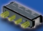
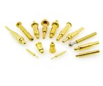
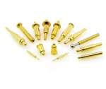
2nd method u can use pogo pins. variety of pogo pins are available u can see some of them in the below image

Pogo-Pin-Connector-BIP-Series-.jpg

then u need to do a connector something like this

7_1250804103.png

and on the PCB prog points should be tre to prog it.

Ref: https://www.microchip.com/forums/m440903-p2.aspx

instead of pogo connector u can use some other connector but it should have same function ex battery connector as follows

Battery-connector.jpg

this connector also has flexibility when u touch. these type of connectors available different size. u can select one of them as u like or suit ur application.
I hope as much as small it i'll be good for u.

If u need some more suggestion post ur schematic and pcb. so that we can suggest u the best as well I can suggest u how to avoid jumpers on prog pins.
 

I had considered this, but the size of my PCB is 42x14 MM, there is absolutely no space for connectors. The entire PCB is to be inserted into a tube of diameter 14.50 MM.

thanks for the response....
 

I use small connector for programming SMD uCs. Connector have 6 pins and have dimensions 4,2mm height, 3,2mm wide. Also SMD variant of connector exist.

Several times I use flat cable and small flat cable connector, and I must say that I am satisfied.

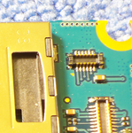
If there is no space on PCB at all you can make soldering point for ISP for tiny wires, or you can use very small connectors which is used in Samsung phones for JTAG.

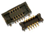
Connector is :

board-to-FPC
A4S Series

Socket : AXE512124
Header : AXE612124

Panasonic Electric Works
https://www.panasonic-electric-works.com

pp_65316_a4s.jpg
 

Attachments

  • ISP Connector Wires - SU06.pdf
    604.7 KB · Views: 48
  • ISP Connector PCB - WU06S.pdf
    594.4 KB · Views: 42
  • ds_65316_en_a4s.pdf
    782.4 KB · Views: 54
  • ds_65312_en_f4s.pdf
    920.3 KB · Views: 40

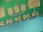
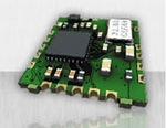
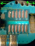
on the edge of the PCB if u make something like this

WxdyS.jpg

BGA_PCB.jpg

53nPk.png

use some mating connector something like this

imagesCAEK6G5Z.jpg

something like this u can extract from Mobile components.

during programming keep press it (no need to insert). that's enough.


still if u need some more ideas pls let us know.
 

on the edge of the PCB if u make something like this

View attachment 90305

View attachment 90306

View attachment 90307

use some mating connector something like this

View attachment 90308

something like this u can extract from Mobile components.

during programming keep press it (no need to insert). that's enough.


still if u need some more ideas pls let us know.

Its interesting but require pro maded PCB with galvanisation and precisely processed PCB edges. It is difficult to make at home, but in any case its interesting.
 
Last edited:

Just use exising through hole component legs or tiny pads and use spring loaded PCB probes. The probes push against the pads/legs and are connected to the Pickit not the PCB itself. If you are making large quantities, build a simple jig to hold the probes and locate the board over them. It takes only a few seconds then to program each board. I've done this with PCBs with 1,000+ test connections so a Pickit should be very simple.

Brian.
 

Just use exising through hole component legs or tiny pads and use spring loaded PCB probes. The probes push against the pads/legs and are connected to the Pickit not the PCB itself. If you are making large quantities, build a simple jig to hold the probes and locate the board over them. It takes only a few seconds then to program each board. I've done this with PCBs with 1,000+ test connections so a Pickit should be very simple.

Yes that is what I am looking for. I have made some pads on the PCB, I will use a connector that will touch this pad for programming.

Thanks everyone for the tips..

- - - Updated - - -

Just use exising through hole component legs or tiny pads and use spring loaded PCB probes. The probes push against the pads/legs and are connected to the Pickit not the PCB itself. If you are making large quantities, build a simple jig to hold the probes and locate the board over them. It takes only a few seconds then to program each board. I've done this with PCBs with 1,000+ test connections so a Pickit should be very simple.

Yes that is what I am looking for. I have made some pads on the PCB, I will use a connector that will touch this pad for programming.

Thanks everyone for the tips..
 

I make using connectors POGO PINS in a JIG of acrylic.
I do in PCB TEST-POINTS (small solder points).
like this **broken link removed**
 

I make using connectors POGO PINS in a JIG of acrylic.
I do in PCB TEST-POINTS (small solder points).
like this **broken link removed**

The pins are big, but I think the concept looks good.

You might also consider this ready-made ICD adaptor **broken link removed**

Yes this is better, I could modify my PCB...

thanks for the tips...
 

The POGO PIN don't have only one type!!!

Have various types.

- - - Updated - - -

The POGO PIN don't have only one type!!!

Have various types.
 

The POGO PIN don't have only one type!!!

Have various types.

Yes. variety of pogo pins are available as I mensioned in 2nd post.


Attachments

  • Pogo-Pin-Connector-BIP-Series-.jpg
    Pogo-Pin-Connector-BIP-Series-.jpg
    37 KB · Views: 97

Status
Not open for further replies.

Similar threads

Part and Inventory Search

Welcome to EDABoard.com

Sponsor

Back
Top