Continue to Site

Welcome to EDAboard.com

Welcome to our site! EDAboard.com is an international Electronics Discussion Forum focused on EDA software, circuits, schematics, books, theory, papers, asic, pld, 8051, DSP, Network, RF, Analog Design, PCB, Service Manuals... and a whole lot more! To participate you need to register. Registration is free. Click here to register now.

Idea about RMP calculation

Status
Not open for further replies.

thebadtall

Full Member level 6
Full Member level 6
Joined
May 17, 2012
Messages
339
Helped
12
Reputation
24
Reaction score
12
Trophy points
1,308
Location
Hellas
Visit site
Activity points
3,605
Hello I would like to calculate the RPM's of my old vespino.
Since it is difficult to screw an encoder in the stator, I thought of
measuring the ac voltage (of generator) through a 10k voltage divider and measuring the peak voltage phase time , or using the pulseIn command with arduino.
Or using interrupt Rising or Falling.

Is that a good approach ? Should I use another approach, ie measuring the phase time from an optoisolator ?

Thank you
 

Hi,

Have you tried using some insulated wire coiled around the ht lead or a connection the low tension contact breaker if it uses one ?
 

No, I havent yet started. I am thinking if voltage measuring is a good approach
 

No, I havent yet started. I am thinking if voltage measuring is a good approach[/QUOTE

Hi,

Would have thought it has some form of voltage limiter fitted to avoid blowing things if it was over revved ?
Similarly if it cannot push out a good voltage at lower revs you are going to have a flat battery / poor lights etc.
 

Yes this is a nice approach too. Do you mean to read the coil from stator wich feeds the ignition coil ?

However, there is no regulator or capacitor or anything in the alternator wiring as it is the old 6volt vespa

- - - Updated - - -

Would have thought it has some form of voltage limiter fitted to avoid blowing things if it was over revved ?
Similarly if it cannot push out a good voltage at lower revs you are going to have a flat battery / poor lights etc.

Hello, it hasn't protection, no battery or limiter. Indeed at low rpm lights blink :p
 

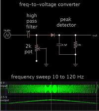
Here is a simple frequency-to-voltage converter, made from a high-pass filter, followed by a peak detector.


By careful adjusting of the rolloff curve, you can obtain a response which is reasonably linear.

Because of the diode, the meter may show a zero reading at idle rpm. This might be cured by making the peak detector from a transistor.
 

Status
Not open for further replies.

Similar threads

Part and Inventory Search

Welcome to EDABoard.com

Sponsor

Back
Top