shreyas.p
Newbie level 3
Hello
I have written a simple code to read the data present on PCF8574 pins and display it on port 2.
In my project, I have 8 switches connected to PCF8574. And I want to read the status of switches and display it on Port 2.
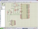
The following code is working perfectly for WRITE operation. When I write the data 01010101 to PCF8574, it is working (see attached image). To test the read operation, I connected the pins of PCF8574 to vcc and ground to generate a pattern (01010101). But it is not being read.
Here is the code i'm using:
;--------------------------------------
; CODE
; (address pins of PCF8574 are connected to ground)
;--------------------------------------
var1 equ r2
temp equ r4
delay equ r1
sda EQU P1.0
scl EQU P1.1
ORG 0000H
AJMP MAIN
MAIN:
setb sda
setb scl
jnb sda $
setb scl $
mov sp,#50H
acall start
mov a,#40h ; device address of PCF8574 (write operation LSB = 0)
acall send_byte
acall acknowledge
acall start
mov a,#41H ; read operation (LSB=1)
acall send_byte
acall acknowledge
acall read_byte
mov P2,A
acall stop
ret
;---------------------------------------
;SUBROUTINES:
;---------------------------------------
send_byte: mov R0,#08h ; setup count
next_bit:
acall wait_halfbit
rlc A ; rotate next bit into carry
mov SDA,C ; set IIC data to carry value
setb SCL ; set IIC clock
acall wait_halfbit ; wait
clr SCL ; drop clock. signals receiver to sample data
djnz R0,next_bit ; do next bit
setb SDA ; idle the data line
ret
read_byte: mov r0,#08H
mov a,#00h
next:
acall wait_halfbit
mov C,sda
setb scl
acall wait_halfbit
clr scl
rrc A
djnz r0, next
setb sda
acall acknowledge
ret
start:
acall wait_halfbit
clr SDA
clr SCL
ret
stop:
clr SDA
clr SDA ; stop bit
setb SCL
acall wait_halfbit
setb SDA
clr SCL
ret
acknowledge:
setb SCL
acall wait_halfbit
clr SCL
RET
wait_halfbit:
nop
nop
nop
nop
ret
delayms: ; delay of 10ms (however i hven't used it in this code)
mov var1,#230
d:
nop
nop
djnz var1,d
djnz 10,delayms
ret
end
;---------------------------------------
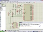
Also I'm getting a message saying
"Simulation is not running in real time due to excessive CPU load"
What does this mean?
I haven't executed this code on breadboard. I'm just testing it on Proteus.
I have written a simple code to read the data present on PCF8574 pins and display it on port 2.
In my project, I have 8 switches connected to PCF8574. And I want to read the status of switches and display it on Port 2.
The following code is working perfectly for WRITE operation. When I write the data 01010101 to PCF8574, it is working (see attached image). To test the read operation, I connected the pins of PCF8574 to vcc and ground to generate a pattern (01010101). But it is not being read.
Here is the code i'm using:
;--------------------------------------
; CODE
; (address pins of PCF8574 are connected to ground)
;--------------------------------------
var1 equ r2
temp equ r4
delay equ r1
sda EQU P1.0
scl EQU P1.1
ORG 0000H
AJMP MAIN
MAIN:
setb sda
setb scl
jnb sda $
setb scl $
mov sp,#50H
acall start
mov a,#40h ; device address of PCF8574 (write operation LSB = 0)
acall send_byte
acall acknowledge
acall start
mov a,#41H ; read operation (LSB=1)
acall send_byte
acall acknowledge
acall read_byte
mov P2,A
acall stop
ret
;---------------------------------------
;SUBROUTINES:
;---------------------------------------
send_byte: mov R0,#08h ; setup count
next_bit:
acall wait_halfbit
rlc A ; rotate next bit into carry
mov SDA,C ; set IIC data to carry value
setb SCL ; set IIC clock
acall wait_halfbit ; wait
clr SCL ; drop clock. signals receiver to sample data
djnz R0,next_bit ; do next bit
setb SDA ; idle the data line
ret
read_byte: mov r0,#08H
mov a,#00h
next:
acall wait_halfbit
mov C,sda
setb scl
acall wait_halfbit
clr scl
rrc A
djnz r0, next
setb sda
acall acknowledge
ret
start:
acall wait_halfbit
clr SDA
clr SCL
ret
stop:
clr SDA
clr SDA ; stop bit
setb SCL
acall wait_halfbit
setb SDA
clr SCL
ret
acknowledge:
setb SCL
acall wait_halfbit
clr SCL
RET
wait_halfbit:
nop
nop
nop
nop
ret
delayms: ; delay of 10ms (however i hven't used it in this code)
mov var1,#230
d:
nop
nop
djnz var1,d
djnz 10,delayms
ret
end
;---------------------------------------
Also I'm getting a message saying
"Simulation is not running in real time due to excessive CPU load"
What does this mean?
I haven't executed this code on breadboard. I'm just testing it on Proteus.
Attachments
Last edited: