Continue to Site

Welcome to EDAboard.com

Welcome to our site! EDAboard.com is an international Electronics Discussion Forum focused on EDA software, circuits, schematics, books, theory, papers, asic, pld, 8051, DSP, Network, RF, Analog Design, PCB, Service Manuals... and a whole lot more! To participate you need to register. Registration is free. Click here to register now.

[PIC] i2c interface with pic18F24k40

Status
Not open for further replies.

ajit_nayak87

Member level 5
Joined
Oct 30, 2017
Messages
86
Helped
1
Reputation
2
Reaction score
1
Trophy points
8
Activity points
981
Dear all
i am trying to interface with 24lc08 with pic18F24k series . i am using XC8 Compiler V2.05/ MPLAB X IDE 5.15 . here i am attached sample code .

I am trying to write into eeprom location and read and display on seven segment display. with below code it display 00
i am using mcc generated file to read and write operation . the code works well with ds1307. how to provide slave address and start address for location

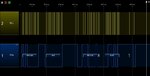
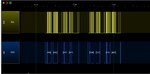
if i used logic analyzer i will get not acknowledge from slave device.

C:
#include "mcc_generated_files/mcc.h"
#include"mcc_generated_files/examples/i2c1_master_example.h"


unsigned int i=0;
unsigned int k=0;
unsigned int count;

unsigned int x;

#define LED RC7

#define CONTROLREG 0xFF
#define SDA            RC4                // Data pin for i2c
#define SCK            RC3                // Clock pin for i2c
#define SDA_DIR        TRISC4            // Data pin direction
#define SCK_DIR        TRISC3            // Clock pin direction

#define I2C_SPEED    150                // kbps  

unsigned short int cnt, num,Dgt=0;;
unsigned short int temp1,temp2,temp3;

int sec;
int min;
int hour;
int date;
int month;
int year;
int day;
int temp=0;
int r_data;
#define Seg1 0x01
#define Seg2 0x02
#define Seg3 0x04
#define Seg4 0x08
#define Seg5 0x10
#define Seg6 0x20


unsigned char Flag_Update=0;


void Delay(unsigned int k) {
    unsigned  int j;
    for(j=0; j<k; j++);
}


void SetSeg(unsigned short data, unsigned  short segno)

{
    switch(data) {
        case 0:
            PORTB = 0x3F;
            break;
        case 1:
            PORTB = 0x06;
            break;
        case 2:
            PORTB = 0x5B;
            break;
        case 3:
            PORTB = 0x4F;
            break;
        case 4:
            PORTB = 0x66;
            break;
        case 5:
            PORTB = 0x6D;
            break;
        case 6:
            PORTB = 0x7D;
            break;
        case 7:
            PORTB = 0x07;
            break;
        case 8:
            PORTB = 0x7F;
            break;
        case 9:
            PORTB = 0X6F;
            break;
        default :
            PORTB = 0X00;
            break;
    }

    if(segno==1) {
        PORTA = Seg4;
    }
    if(segno==2) {
        PORTA = Seg3;
    }
    if(segno==3) {
        PORTA = Seg2;
    }
    if(segno==4) {
        PORTA = Seg1;
    }

    if(segno==5) {
        PORTC=0X00;
        PORTC = 0x40;//DP2 fourth Segment

        // PORTCbits.RC5=1;
    }

    if(segno==6) {
        PORTC=0X00;
        PORTC= 0x20;//DP2 third Segment

        //PORTCbits.RC6=1;
    }


    if(segno==7) {
        PORTA=0X00;
        PORTA = Seg5; //DP2 Second Segment
        //     PORTAbits.RA4=1;
    }

    if(segno==8) {
        PORTA=0X00;
        PORTA = Seg6; //DP2 First Segment
        // PORTAbits.RA5=1;
    }

}


unsigned int bcdtodecimal(unsigned int bcd) {
    unsigned int decimal;
    decimal = (((bcd & 0xF0) >> 4) * 10) + (bcd & 0x0F);
    return decimal;
}


void ISR_Routine(void) {
    if(PIR0bits.TMR0IF==1) {
        PIR0bits.TMR0IF = 0;
        count= count+1;
        if(count>=2) {
            LED=!LED;
            Flag_Update=1;
            count=0;


        }
    }


}


void main(void) {
    // Initialize the device
    SYSTEM_Initialize();
    INTCONbits.GIE=1;
    INTCONbits.PEIE=1;


    // If using interrupts in PIC18 High/Low Priority Mode you need to enable the Global High and Low Interrupts
    // If using interrupts in PIC Mid-Range Compatibility Mode you need to enable the Global and Peripheral Interrupts
    // Use the following macros to:

    // Enable the Global Interrupts
    //INTERRUPT_GlobalInterruptEnable();

    // Disable the Global Interrupts
    //INTERRUPT_GlobalInterruptDisable();

    // Enable the Peripheral Interrupts
    //INTERRUPT_PeripheralInterruptEnable();

    // Disable the Peripheral Interrupts
    //INTERRUPT_PeripheralInterruptDisable();


    I2C1_Initialize();

//I2C1_Read2ByteRegister(0XA0,0x02);

    I2C1_Write2ByteRegister(0XA0,0x02,0x58);


    while (1)


    {

        sec=I2C1_Read2ByteRegister(0XA0,0x02);


        if(Flag_Update==1) {
            /*SetSeg(min >> 4,4);
            __delay_ms(10);
            SetSeg(min & 0x0f,3);
            __delay_ms(10);*/
            SetSeg(sec >> 4,2);
            __delay_ms(10);
            SetSeg(sec & 0x0f,1);
            __delay_ms(10);
            Flag_Update = 0;    //ready for next update
        }


    }
}
 

Hi,

you did not care about R/W bit in Slave_address_byte (Control_byte)

in binary the address is: 0b 1010 xBBR
where
x = don´t care
B = Block select Bits
R = READ/WRITE bit.

so to read the byte you need transmit 0b 1010 x001 usually: 0b 1010 0001 which is 0XA1

***
Additionally you need to choose how you want to read:
* current address
* Random address
* Sequential address


Please follow the datasheet Figures 8-1, 8-2 and 8-3

We all need to read the datasheet and follow it´s instructions.


Klaus
 

I'm not familiar with MPLAB-X MCC, but the code looks reasonable at first sight.

Do you see NAK already during address phase? Is E2 chipselect connected to ground to support the used address?
--- Updated ---

you did not care about R/W bit in Slave_address_byte (Control_byte)
Don't think so. I2C1_Read2ByteRegister() is a high level function issuing combined address write and data read. It does the selection of read and write bit internally.
--- Updated ---

If I see right, address in MCC library is a 7-bit value, thus correct 24C08 base address value would be 0x50.
--- Updated ---

Look at i2c_master.c

C:
static i2c_fsm_states_t I2C_DO_SEND_ADR_READ(void)
{
    I2C_Status.addressNackCheck = 1;
    I2C_MasterSendTxData(I2C_Status.address << 1 | 1);
    return I2C_RCEN;
}
 
Last edited:

I am using MCC generated file.
Yes I have connected to wp pins connected to. Ground.which means memory bit is enable to write

A0/a1/a2 are pulled up 5v
SDA and scl pins are pulled up 10k resistor

I have another rtc device pc8563 where I used pull up 4.75k resistor where I could able to communicate with same library.
I am using same library for communicated to 24lc08 device.

I am trying to communicate independently.once they communication independent then I will bring them together.

Yes few people recommend to use 0x50 and 0x53 . But I don't know how they got these value. Because data sheet says 0xA0 and 0xA1

Is there any thing do with speed of i2c. In future I wanted to communicate with both device same speed.

As per data sheet 24lc08 device

10kohm for 100khz
2kohm for 400khz
 

Yes few people recommend to use 0x50 and 0x53 . But I don't know how they got these value. Because data sheet says 0xA0 and 0xA1
As per data sheet 24lc08 device


0xA0 >>1 => 0x50 = device adress 7 bits used by MCC
global 8 bits adress = 0x50 <<1 + bit R/W => 0xA0 to write 0xA1 to read

be carrefull, somme RTC board as RTC DS3231 board have allready and EEPROM on it
this EEPROM can do some conflict adress with another external Eeprom with same base adress
in this case , just modify A0 A1 strap on eeprom pin to change the base adress
 

is it correct . i am not using DS3231 , iam using NXP 8563 RTC device . its slave address is different.


Code:
#define Slave address 0X50
#define start addres 0X00

void main(void) {
    // Initialize the device
    SYSTEM_Initialize();
    INTCONbits.GIE=1;
    INTCONbits.PEIE=1;

    I2C1_Initialize();
I2C1_Write1ByteRegister( Slave address + (start address >> 8),(start_address & 0xFF),0x01);
    while (1)
    {

        sec=I2C1_Read1ByteRegister(0XA1+(start address >> 8),0x00);


        if(Flag_Update==1) {
            /*SetSeg(min >> 4,4);
            __delay_ms(10);
            SetSeg(min & 0x0f,3);
            __delay_ms(10);*/
            SetSeg(sec >> 4,2);
            __delay_ms(10);
            SetSeg(sec & 0x0f,1);
            __delay_ms(10);
            Flag_Update = 0;    //ready for next update
        }


    }
}
--- Updated ---

i have connected A0/A1/A2 shorted to ground pin . as per datasheet it enable write eeprom bits.
 

Yes few people recommend to use 0x50 and 0x53 . But I don't know how they got these value. Because data sheet says 0xA0 and 0xA1
You'll know if you review the MCC generate code. Analyzing the logic analyzer output will also show you how MCC is interpreting the address value.

You didn't yet answer the other question in post #3, when do you see NAK in the protocol?
 

I have put the code and check when I used logical analyzer with
I2C1_Write2ByteRegister(0X50,0x02,0x58)
I could able to get proper clock pulse
I could able to get start signal followed by 0x50 but when device has to send acknowledge device sending me not acknowledge rapidly.
These instructions are repeatedly execution
So bit confuse which slave address need to share
 

but when device has to send acknowledge device sending me not acknowledge rapidly
Sorry, don't understand what you mean, what is rapidly in this context? Please show logic analyzer recording.
 

Here is sample code . i could able to get response . I am trying into one memory address and response same time. Output form is attached.

HOW could i access multiple EEPROM location.below i could able to access only single location not multiple location.How should i write one after the other

i would like to write into multiple EEPROM location and same thing shall be read from eeprom display on seven segment display

Code:
void main(void)
{
    // Initialize the device
    SYSTEM_Initialize();
    INTCONbits.GIE=1;
    INTCONbits.PEIE=1;
    
 I2C1_Initialize(); 
  
   I2C1_Write1ByteRegister(0X50+(StartAddr>>8),(StartAddr&0XFF),0x35);
   I2C1_Write1ByteRegister(0X51+(StartAddr>>8),(StartAddr&0XFF),0x10);

    while (1)
        
        
    {
  
        sec=I2C1_Read1ByteRegister(0X50+(StartAddr>>8),(StartAddr&0XFF));
        min=I2C1_Read1ByteRegister(0X51+(StartAddr>>8),(StartAddr&0XFF));
      
       if(Flag_Update==1) {
            SetSeg(min >> 4,4);
            __delay_ms(10);
            SetSeg(min & 0x0f,3);
            __delay_ms(10);
            SetSeg(sec >> 4,2);
            __delay_ms(10);
            SetSeg(sec & 0x0f,1);
            __delay_ms(10);
            Flag_Update = 0;    //ready for next update
        }           
        
      
    }
  
  
}


working code

Code:
unsigned int i=0;
unsigned int k=0;
unsigned int count;
unsigned int x;
#define LED RC7
#define StartAddr 0X00
#define CONTROLREG 0xFF
#define SDA            RC4                // Data pin for i2c
#define SCK            RC3                // Clock pin for i2c
#define SDA_DIR        TRISC4            // Data pin direction
#define SCK_DIR        TRISC3            // Clock pin direction

#define I2C_SPEED    150                // kbps   

unsigned short int cnt, num,Dgt=0;;
unsigned short int temp1,temp2,temp3;

int sec;
int min;
int hour;
int date;
int month;
int year;
int day;
int temp=0;
int r_data;
#define Seg1 0x01
#define Seg2 0x02
#define Seg3 0x04
#define Seg4 0x08
#define Seg5 0x10
#define Seg6 0x20


unsigned char Flag_Update=0;

void Delay(unsigned int k) {
    unsigned  int j;
    for(j=0; j<k; j++);
}

void SetSeg(unsigned short data, unsigned  short segno)

{
    switch(data) {
        case 0:
            PORTB = 0x3F;
            break;
        case 1:
            PORTB = 0x06;
            break;
        case 2:
            PORTB = 0x5B;
            break;
        case 3:
            PORTB = 0x4F;
            break;
        case 4:
            PORTB = 0x66;
            break;
        case 5:
            PORTB = 0x6D;
            break;
        case 6:
            PORTB = 0x7D;
            break;
        case 7:
            PORTB = 0x07;
            break;
        case 8:
            PORTB = 0x7F;
            break;
        case 9:
            PORTB = 0X6F;
            break;
        default :
            PORTB = 0X00;
            break;
    }

    if(segno==1) {
        PORTA = Seg4;
    }
    if(segno==2) {
        PORTA = Seg3;
    }
    if(segno==3) {
        PORTA = Seg2;
    }
    if(segno==4) {
        PORTA = Seg1;
    }

    if(segno==5) {
        PORTC=0X00;
        PORTC = 0x40;//DP2 fourth Segment

        // PORTCbits.RC5=1;
    }

    if(segno==6) {
        PORTC=0X00;
        PORTC= 0x20;//DP2 third Segment

        //PORTCbits.RC6=1;
    }


    if(segno==7) {
        PORTA=0X00;
        PORTA = Seg5; //DP2 Second Segment
        //     PORTAbits.RA4=1;
    }

    if(segno==8) {
        PORTA=0X00;
        PORTA = Seg6; //DP2 First Segment
        // PORTAbits.RA5=1;
    }

}


unsigned int bcdtodecimal(unsigned int bcd) {
    unsigned int decimal;
    decimal = (((bcd & 0xF0) >> 4) * 10) + (bcd & 0x0F);
    return decimal;
}

void ISR_Routine(void) {
    if(PIR0bits.TMR0IF==1) {
        PIR0bits.TMR0IF = 0;
        count= count+1;
        if(count>=2) {
            LED=!LED;
            Flag_Update=1;
            count=0;
        }
    }

}


void main(void) {
    // Initialize the device
    SYSTEM_Initialize();
    INTCONbits.GIE=1;
    INTCONbits.PEIE=1;
    I2C1_Initialize();
    I2C1_Write1ByteRegister(0X50+(StartAddr>>8),(StartAddr&0XFF),0x35);
    
    
    while (1) {
        sec=I2C1_Read1ByteRegister(0X50+(StartAddr>>8),(StartAddr&0XFF));
        if(Flag_Update==1) {
            SetSeg(min >> 4,4);
            __delay_ms(10);
            SetSeg(min & 0x0f,3);
            __delay_ms(10);
            SetSeg(sec >> 4,2);
            __delay_ms(10);
            SetSeg(sec & 0x0f,1);
            __delay_ms(10);
            Flag_Update = 0;    //ready for next update
        }

    }
}
 

Attachments

  • OUTPUT.JPG
    OUTPUT.JPG
    66.3 KB · Views: 119

The second write procedure might fail because it's not waiting for the termination of first write. Review 24c08 datasheet in this regard. ACK polling has to performed, don't expect that it's done in the MCC routines automatically. You can insert wait of 5 ms (maximal duration of page write) before the second write as a quick workaround.
 

My question is if RTC device could take response why cant EEPROM. where i am writing RTC date and time one after the other and read also doing same time.

Code:
void main(void) {
    // Initialize the device
    SYSTEM_Initialize();
    INTCONbits.GIE=1;
    INTCONbits.PEIE=1;


    I2C1_Initialize();

//I2C1_Read2ByteRegister(0XA0,0x02);


    I2C1_Write1ByteRegister(0X50+(StartAddr>>8),(StartAddr&0XFF),0x35);
    I2C1_Write1ByteRegister(0X50+((StartAddr+1)>>8),((StartAddr+1)&0XFF),0x02);

    while (1)


    {     
      
        
        sec=I2C1_Read1ByteRegister(0X50+(StartAddr>>8),(StartAddr&0XFF));
        min=I2C1_Read1ByteRegister(0X50+((StartAddr+1)>>8),(StartAddr+1)&0XFF);
        //min=I2C1_Read1ByteRegister(0X51+(StartAddr>>8),(StartAddr&0XFF));

        if(Flag_Update==1) {
            SetSeg(min >> 4,4);
            __delay_ms(10);
            SetSeg(min & 0x0f,3);
            __delay_ms(10);
            SetSeg(sec >> 4,2);
            __delay_ms(10);
            SetSeg(sec & 0x0f,1);
            __delay_ms(10);
            Flag_Update = 0;    //ready for next update
        }


    }


}
 

Attachments

  • Out1.JPG
    Out1.JPG
    65.7 KB · Views: 86

My question is if RTC device could take response why cant EEPROM. where i am writing RTC date and time one after the other and read also doing same time.
EEPROM can, but you need to observe the datasheet requirements.

The logic analyzer recording in post #10 shows read
not write access.
 

Here is setup for PIC18F24k40 . i have used 1ms timer interrupt 100khz frequency. I have tested independently 2 i2c device 24lc08 & PCF8563 . both device working normally. But when SDA and SCL lines shorted . RTC display get slowdown.
Sec parameter in display used to display 01 sec increment but after short it incrementing but jumping arbitaty . weather it problem in hardware or software . both device working at speed of 100Khz .
weather 4.75k should be replace wth 10k resistor for PCF8563 ?? or only one line of SDA /SCL pull up is efficient


Code:
#include "mcc_generated_files/mcc.h"
#include"mcc_generated_files/examples/i2c1_master_example.h"

unsigned int i=0;
unsigned int k=0;
unsigned int count;
unsigned int x;
#define LED RC7
#define CONTROLREG 0xFF
#define SDA            RC4                // Data pin for i2c
#define SCK            RC3                // Clock pin for i2c
#define SDA_DIR        TRISC4            // Data pin direction
#define SCK_DIR        TRISC3            // Clock pin direction

#define I2C_SPEED    150                // kbps   

unsigned short int cnt, num,Dgt=0;;
unsigned short int temp1,temp2,temp3;

int sec;
int min;
int hour;
int date;
int month;
int year;
int day;
int temp=0;
int r_data;
#define Seg1 0x01
#define Seg2 0x02
#define Seg3 0x04
#define Seg4 0x08
#define Seg5 0x10
#define Seg6 0x20
#define Seg7 0x40
#define Seg8 0x80

#define StartAddr 0X00


unsigned char Flag_Update=0;


void Delay(unsigned int k) {
    unsigned  int j;
    for(j=0; j<k; j++);
}

void SetSeg(unsigned short data, unsigned  short segno)

{
    switch(data) {
        case 0:
            PORTB = 0x3F;
            break;
        case 1:
            PORTB = 0x06;
            break;
        case 2:
            PORTB = 0x5B;
            break;
        case 3:
            PORTB = 0x4F;
            break;
        case 4:
            PORTB = 0x66;
            break;
        case 5:
            PORTB = 0x6D;
            break;
        case 6:
            PORTB = 0x7D;
            break;
        case 7:
            PORTB = 0x07;
            break;
        case 8:
            PORTB = 0x7F;
            break;
        case 9:
            PORTB = 0X6F;
            break;
        default :
            PORTB = 0X00;
            break;
    }

    if(segno==1) {
        PORTA = Seg4;
    }
    if(segno==2) {
        PORTA = Seg3;
    }
    if(segno==3) {
        PORTA = Seg2;
    }
    if(segno==4) {
        PORTA = Seg1;
    }

    if(segno==5) {
        PORTA = Seg5;
    }

    if(segno==6) {
        PORTA = Seg6;
    }


    if(segno==7) {

        PORTA = Seg7; //DP2 Second Segment

    }

    if(segno==8) {

        PORTA = Seg8;

    }

}


unsigned int bcdtodecimal(unsigned int bcd) {
    unsigned int decimal;
    decimal = (((bcd & 0xF0) >> 4) * 10) + (bcd & 0x0F);
    return decimal;
}


void ISR_Routine(void) {
    if(PIR0bits.TMR0IF==1) {
        PIR0bits.TMR0IF = 0;
        count= count+1;
        if(count>=1) {
            LED=!LED;
            Flag_Update=1;
            count=0;


        }
    }


}


unsigned int MIN;
unsigned int SEC;


void main(void) {
    // Initialize the device
    SYSTEM_Initialize();
    INTCONbits.GIE=1;
    INTCONbits.PEIE=1;
    I2C1_Initialize();
    I2C1_Write1ByteRegister(0X51,0x02,0x58);// Second
    I2C1_Write1ByteRegister(0X51,0x03,0x58);// minute
    I2C1_Write1ByteRegister(0X51,0x04,0x01);// hour
    I2C1_Write1ByteRegister(0X51,0x05,0x01);
    I2C1_Write1ByteRegister(0X51,0x06,0x02);
    I2C1_Write1ByteRegister(0X51,0x07,0x03);
    I2C1_Write1ByteRegister(0X51,0x08,0x10);
    I2C1_Write1ByteRegister(0X50+(StartAddr>>8),(StartAddr&0XFF),0x35);
    I2C1_Write1ByteRegister(0X50+((StartAddr+1)>>8),((StartAddr+1)&0XFF),0x02);

    while (1)


    {

        sec=I2C1_Read1ByteRegister(0X51,0x02);
        min=I2C1_Read1ByteRegister(0X51,0x03);
        MIN=I2C1_Read1ByteRegister(0X50+(StartAddr>>8),(StartAddr&0XFF));
        I2C1_MasterSendAck();
        SEC=I2C1_Read1ByteRegister(0X50+((StartAddr+1)>>8),(StartAddr+1)&0XFF);

        SetSeg(min >> 4,4);
        __delay_ms(2);
        SetSeg(min & 0x0f,3);
        __delay_ms(2);
        SetSeg(sec >> 4,2);
        __delay_ms(2);
        SetSeg(sec & 0x0f,1);
        __delay_ms(2);
        Flag_Update = 0;    //ready for next update


        SetSeg(MIN >> 4,6);
        __delay_ms(2);
        SetSeg(MIN & 0x0f,5);
        __delay_ms(2);
        SetSeg(SEC>> 4,8);
        __delay_ms(2);
        SetSeg(SEC & 0x0f,7);
        __delay_ms(2);
        Flag_Update = 0;    //ready for next update


    }
}
 

Attachments

  • RTC_device-page-001.jpg
    RTC_device-page-001.jpg
    90 KB · Views: 97

Hi,

Your interrupt is almost useless. It just toggles the port. Variables "count" and "flag_update" are useless.

SDA needs only one pullup. Not 2. 4k7 should be O.K.
SCL needs only one pullup. Not 2. 4k7 should be O.K.

Please check whether this is correct: One WP is pulled low, while the other is pulled down.

As already mentioned: keep on write timing.

And as far as I can see you read and display continously without any delay. (I'd never do this)
A straight forward solution could be to use the INT output of the RTC.

You could also use a software clock that gets synchronized to the RTC once every couple of hours.

Klaus
 

hello,


24C02 WP pin must be tied directly to ground . (remove R1=100k)

I2C1_Write1ByteRegister(0X50+(StartAddr>>8),(StartAddr&0XFF),0x35);
i suppose StartAddr is the adresse builded by the A0,A1,A2 pin for adding device hardware adress (depend of the device type)
but why using StartAddr to designe the device register ?
register adress is not concerned by device adress

if A0,A1,A2 are tied to ground , just use adresse 0x50
or use 0x57 if A0,A1,A2 link are open
I2C1_Write1ByteRegister(0X57, 0 ,0x35); <- more clear 0 =adresse of first device register
 

The code can't work with the current address setting because RTC and EEPROM have overlapping addresses. 24C08 can be set to the alternative address by strapping the address pin to VDD.
 

Status
Not open for further replies.

Similar threads

Part and Inventory Search

Welcome to EDABoard.com

Sponsor

Back
Top