pratzz
Member level 5
Code:
list p=PIC16F877a
#include <p16F877a.inc>
errorlevel -302
__config _HS_OSC & _WDT_OFF & _LVP_OFF
;-------------------------------------------
; SPECIAL FUNCTION REGISTERS
;-------------------------------------------
;*******************Macro definitions*****************************
WRITE_ADDR  equ     b'10100000' ; Control byte for write operations
READ_ADDR   equ     b'10100001' ; Control byte for read operations
rs  equ 2
rw equ 3
en equ 4
;*******************Include file**********************************

;-------------------------------------------
; GENERAL PURPOSE REGISTERS
;-------------------------------------------
		CBLOCK 20h
count
count1
count3
count4
dat
disp
number
bytecount
temp
		ENDC


		ORG 0
		clrf STATUS
		movlw 00
		movwf PCLATH
		goto start
;-------------------------------------------
		org 04
		retfie
;----------------------------------------------

lcd_cmd
        movwf PORTD
        bcf PORTB,rs
        bcf PORTB,rw
        bsf PORTB,en
        call delay
        bcf PORTB,en
        retlw 00h
;------------------------------------------------------------------
lcd_data
        movwf PORTD
        bsf PORTB,rs
        bcf PORTB,rw
        bsf PORTB,en
        call delay
        bcf PORTB,en
        retlw 00h
;------------------------------------------------------------------
lcd_init
        movlw 38h
        call lcd_cmd
        call delay
        movlw 0eh
        call lcd_cmd
        call delay
        movlw 01h
        call lcd_cmd
        call delay
        movlw 06h
        call lcd_cmd
        call delay
        movlw 80h
        call lcd_cmd
        call delay
        call delay
         retlw 00h
;-------------------------------------------------------------------
delay
        movlw 02h
        movwf count3
here2   movlw 0ffh
        movwf count4
here    decfsz count4,1
        goto here
        decfsz count3,1
        goto here2
        retlw 00h
;-----------------------------------------------------------------


initialise
        clrf temp
        clrf count
		bcf STATUS,RP1
		bsf STATUS,RP0
        clrf TRISB
		clrf TRISD
		movlw b'00000111'
		movwf ADCON1
        movlw b'11111111'
        movwf   TRISC               ; Set PORTC to all inputs
        clrf    SSPSTAT             ; Disable SMBus inputs
        bsf     SSPSTAT,SMP         ; Disable slew rate control
        movlw   09h                ; Load 0x18 into WREG
        movwf   SSPADD              ; Setup 100 kHz I2C clock
        clrf    SSPCON2
		bcf     STATUS,RP0
        movlw   b'00101000'
        movwf   SSPCON              ; Enable SSP, select I2C Master mode
        bcf     PIR1,SSPIF          ; Clear SSP interrupt flag
        bcf     PIR2,BCLIF
		retlw 00
;--------------------------------------------------------------
genstart

    bcf     STATUS,RP1
    bcf     STATUS,RP0          ; Select Bank 00
    bcf     PIR1,SSPIF          ; Clear SSP interrupt flag
    bsf     STATUS,RP0          ; Select Bank 01
    bsf     SSPCON2,SEN         ; Generate Start condition
    bcf     STATUS,RP0          ; Select Bank 00
    start_wait
    btfss   PIR1,SSPIF          ; Check if operation completed
    goto    start_wait          ; If not, keep checking
    retlw   0
genstop
    bcf     STATUS,RP1
    bcf     STATUS,RP0          ; Select Bank 00
    bcf     PIR1,SSPIF          ; Clear SSP interrupt flag
    bsf     STATUS,RP0          ; Select Bank 01
    bsf     SSPCON2,PEN         ; Generate Stop condition
    bcf     STATUS,RP0          ; Select Bank 00
stop_wait
    btfss   PIR1,SSPIF          ; Check if operation completed
    goto    stop_wait          ; If not, keep checking
    retlw   00
genrepstart
    bcf     STATUS,RP1
    bcf     STATUS,RP0          ; Select Bank 00
    bcf     PIR1,SSPIF          ; Clear SSP interrupt flag
    bsf     STATUS,RP0          ; Select Bank 01
    bsf     SSPCON2,RSEN        ; Generate Restart condition
    bcf     STATUS,RP0          ; Select Bank 00
    repstart_wait
    btfss   PIR1,SSPIF          ; Check if operation completed
    goto    repstart_wait       ; If not, keep checking

    retlw   0
;-------------------------------------------------------------
receive
    bcf     STATUS,RP1
    bcf     STATUS,RP0          ; Select Bank 00
    bcf     PIR1,SSPIF          ; Clear SSP interrupt flag
    bsf     STATUS,RP0          ; Select Bank 01
    bsf     SSPCON2,RCEN        ; Initiate reception of byte
    bcf     STATUS,RP0          ; Select Bank 00
rx_wait

    btfss   PIR1,SSPIF          ; Check if operation completed
    goto    rx_wait             ; If not, keep checking
    movf    SSPBUF,W           ; Copy byte to WREG
    ;movwf   dat                 ; Copy WREG to datai

    call lcd_data
    bcf     PIR1,SSPIF          ; Clear SSP interrupt flag
    bsf     STATUS,RP0          ; Select Bank 01
    bsf     SSPCON2,ACKEN       ; Generate ACK/NO ACK bit
    bcf     STATUS,RP0          ; Select Bank 00
rx_wait2
    btfss   PIR1,SSPIF          ; Check if operation completed
    goto    rx_wait2            ; If not, keep checking
    movf    dat,w
    call lcd_data
    retlw   0
;-------------------------------------------------------------
transmit

    bcf     STATUS,RP1
    bcf     STATUS,RP0          ; Select Bank 00
    bcf     PIR1,SSPIF          ; Clear SSP interrupt flag
    movf    dat,W           ; Copy dat to WREG
    movwf   SSPBUF              ; Write byte out to device
  tx_wait
    btfss   PIR1,SSPIF          ; Check if operation completed
    goto    tx_wait             ; If not, keep checking
    bcf     PIR1,SSPIF

;-----------------------------------------------------------
    byteread
    call    genstart              ; Generate Start condition

                                       ; Send control byte
    bcf     STATUS,RP0          ; Select Bank 00
    movlw   WRITE_ADDR          ; Load control byte for write
    movwf   dat                    ; Copy to datao for output
    call    transmit                 ; Send control byte to device

    ; Send word address high byte
    bcf     STATUS,RP0          ; Select Bank 00
    movlw   12h               ; Load 0x5A for word address
    movwf   dat               ; Copy to datao for output
    call    transmit                 ; Send high byte to device

                                ; Send word address low byte
    call    genrepstart            ; Generate Restart condition

                                ; Send control byte
    bcf     STATUS,RP0          ; Select Bank 00
    movlw   READ_ADDR           ; Load control byte for read
    movwf   dat                 ; Copy to datao for output
    call    transmit                 ; Send control byte to device
                               ; Read data byte
    bsf     STATUS,RP0          ; Select Bank 01
    bsf     SSPCON2,ACKDT       ; Select to send NO ACK bit
    bcf     STATUS,RP0
    call    receive              ; Read data byte from device
    call    genstop               ; Generate Stop condition

    retlw   0
    pageread
    bcf     STATUS,RP0          ; Select Bank 00
    movlw   08h
    movwf   bytecount           ; Initialize counter to 16 bytes

    call    genstart              ; Generate start bit
                                ; Now send the control byte
                                ; for a write, to set address
    bcf     STATUS,RP0          ; Select Bank 00
    movlw   WRITE_ADDR
    movwf   dat               ; Copy control byte to buffer
    call    transmit                 ; Output control byte to device

                                ; Send word address high byte
    bcf     STATUS,RP0          ; Select Bank 00
    movf    count,W                ; Use 0x5A for address to send
    movwf   dat                       ; Load 0x00 into datao
    call    transmit                  ; Send high byte to device

                                ; Send word address low byte
    bcf     STATUS,RP0          ; Select Bank 00
    call    genrepstart            ; Generate another start bit
                                ; to switch to read mode
    bcf     STATUS,RP0          ; Select Bank 00
    movlw   READ_ADDR
    movwf   dat               ; Copy control byte to buffer
    call    transmit                 ; Output control byte to device

rxbyte
                                ; Finally, read the data byte
    bcf     STATUS,RP0          ; Select Bank 00
    decfsz  bytecount,F         ; Check if finished looping
    goto    continue            ; If not finished, keep going
    bsf     STATUS,RP0          ; Select Bank 01
    bsf     SSPCON2,ACKDT       ; Otherwise, select to send NO ACK bit
    call    receive                  ;   and input final byte from device

    call    genstop               ; Generate stop bit
    retlw   0

continue
    incf count,1
    ;incf count,1
    bsf     STATUS,RP0          ; Select Bank 01
    bcf     SSPCON2,ACKDT       ; Select to send ACK bit
    call    receive                  ; Input data from device
    goto    rxbyte              ; Continue looping
;-------------------------------------------
; Main program starts
;-------------------------------------------
start		call initialise
            call lcd_init

            call pageread
            call delay
            call delay
            call pageread
            movlw 0c0h
            call lcd_cmd
            call delay
            call delay
            call pageread
            call delay
            call delay
            call pageread

 x           goto x
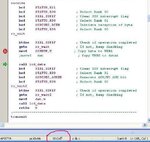
endthe lcd is just diplaying black screen instead of data i hav written into the eeprom
Last edited: