Continue to Site

Welcome to EDAboard.com

Welcome to our site! EDAboard.com is an international Electronics Discussion Forum focused on EDA software, circuits, schematics, books, theory, papers, asic, pld, 8051, DSP, Network, RF, Analog Design, PCB, Service Manuals... and a whole lot more! To participate you need to register. Registration is free. Click here to register now.

I2c communication for longer distance

Status
Not open for further replies.

zuirgham

Junior Member level 3
Joined
Mar 19, 2019
Messages
31
Helped
0
Reputation
0
Reaction score
1
Trophy points
8
Activity points
368
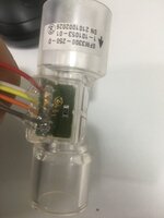
I'm designing a circuit for a digital flow meter. This is the part being used(SFM3300-D). The Sensor is being designed to be used with ventilator externally.

according to datasheet, It says using I2C communication, wire length should not be more than 30cm. But as we know, the patient tube is itself of minimum 2metrs in length.

I want to read the sensor data inside the device, which is Approx 2metrs away from the sensor. How do i do it? Any ideas on how to proceed? please do share.


Datasheet is attached for reference.
 

Attachments

  • Sensirion_Mass_Flow_Meters_SFM3300_Datasheet.pdf
    441.9 KB · Views: 248

Hi,

There are dedicated I2C IC to increase possible cable length.

But in your case...since 2m isn't really a long cable
* You could reduce I2C speed (to relax timing)
* use lower value pull up resistors (to improve signal edges)
* use shielded cables (to reduce noise)
* use low capacitance cables (to improve signal edges)
* maybe use a MUX to switch different I2C paths (to decrease overall load)
* maybe adjust I2C supply (pull up) voltage (for best noise margins)

But for sure this means you need to read some datasheets ... to find out the parameters and limits

Klaus
 

The I2C specification doesn't explicitly give a maximal bus length but a maximal capacitance of 400 pF, 2 m would be feasible without I2C extenders in so far. If you design a commercial product, consider that the long I2C bus is likely to fail in EMC tests, e.g. burst and ESD. If your instrument has a continuous metal enclosure, things may be better.
 

Hi,

There are dedicated I2C IC to increase possible cable length.

But in your case...since 2m isn't really a long cable
* You could reduce I2C speed (to relax timing)
* use lower value pull up resistors (to improve signal edges)
* use shielded cables (to reduce noise)
* use low capacitance cables (to improve signal edges)
* maybe use a MUX to switch different I2C paths (to decrease overall load)
* maybe adjust I2C supply (pull up) voltage (for best noise margins)

But for sure this means you need to read some datasheets ... to find out the parameters and limits

Klaus
Hi,

Yes i did go through the above ideas. My concern is, as you can see the Flow meter in the picture attached, i cannot do anything on the sensor side, Whatever has to be done, i have to do it in my circuit board which is a ventilator machine.

I referred a few datasheets, where in they were suggesting solutions for both master and slave. Lets say i'm using a bus extender(P82B96), i need to implement at the master as well as slave.

Whatever changes or modifications have to be done, it should be on the PCB side (I2C Master).

Any suggestions considering above scenario, please do share.
 

Attachments

  • thumbnail_IMG_2819.jpg
    thumbnail_IMG_2819.jpg
    146.7 KB · Views: 206

Hi,

There are dedicated I2C IC to increase possible cable length.

But in your case...since 2m isn't really a long cable
* You could reduce I2C speed (to relax timing)
* use lower value pull up resistors (to improve signal edges)
* use shielded cables (to reduce noise)
* use low capacitance cables (to improve signal edges)
* maybe use a MUX to switch different I2C paths (to decrease overall load)
* maybe adjust I2C supply (pull up) voltage (for best noise margins)

But for sure this means you need to read some datasheets ... to find out the parameters and limits

Klaus
Hi,

I have come up with a new plan, i will be using these parts "P82B96" , "P82B715", (should study thier datasheet in detail) for designing circuit.

could you give me any ideas on things i should take care when choosing legthy wires, like taking care of EMC compliance, etc so that signal doesn't gets disturbed or in my case I2C protocol doesn't gets violated.

I'm designing for 2.5meters cable.
 

Hi
Problem with long cable is noise, that effect to reliability of system.
Long cable is like absorption antenna, and you know rf is allaways arround.
I2C is single end power bus, that make unbalance power between end point. Mean has dc current flow on data bus.
Problem happen is GND is not same in End Point. Have different between GND, cause by unbalance dc current x wire resistance/Impedance.
Different GND make wrong logic level, noise from RF make wrong clock/data. ESD/EMI damage input port/IC.
So, need to reduce these effect to maintenaince data:
1 - Use buffer/switch IC to isolate I2C bus to main MCU/Processor to increase reliablity of system. If I2C bus failed, that don't make MCU shutdown. Or system only connect to sensor when need and reduce effect of noise to main/ MCU.
2 - Reduce clock frequency of I2C to reduce effect of unbalance, impedance of long cable. Use multiple strand wire cable to reduce impedance. Larger core size cable.
3 - Add RC subbber at end point, MCU side and sensore side to reduce ringing on bus.
4 - Calculate resonant rf frequency with cable length then add decoupling capacitor at end point (<~xxx pF).
5 - Add accelerator IC to recover edge/streng of pull-up resitor. Because step 3&4 increase capacitor load. Look: https://www.analog.com/en/about-adi...vily-loaded-i2c-smbus-system-reliability.html
6 - Add small ferrite bead on SCL, SDA, GND to reduce common mode noise. Because this is unbalance/ sing-end bus so can't use choke to filter.
7 - Use Vcc 5V higher than 3V3 is better. Check the edge of clock and data with falling edge.
8 - MCU have to config repeat deinit & init_i2c() function after define time or when fail reading event. Some amr-core MCU still run when error but has no operation on I2C bus.
9 - Add more decoupling capacitor for VCC at sensor side.
10 - Add TVS at end point to protect ESD.
11 - Use independent or protected power VCC to supply sensor. This will not make shutdown system if issue happen with cable.
12 - Layout with seperate zone, to reduce effect of noise, ferrite filter, decoupling capacitor, TVS, Accellerator, buffer/switch, independent power supply.

The other solution is use RS485/Rs232 bus, you build a small module to convert I2C to Rs485/232 then connect to main board.
You can also I2C Isolator module to reduce more commond mode noise like https://www.analog.com/en/parametricsearch/11033#/ and power supply need isolation. This make solution cost higher, you can use opto trick to isolated SCL SDA line :) (bidirection line )
 

I concur with @Taihung . I2C is very susceptible to noise , being asymmetric in impedance for "0,1" and cable capacitance loading 100 pF/m whereas low impedance differential is the obvious solution. Interfacing is a big problem, but there are many choices of differential signals, protocols and connectors. e.g. https://learn.sparkfun.com/tutorials/qwiic-differential-i2c-bus-extender-pca9615-hookup-guide/all This is just an idea, not your ideal solution.

1635034070696.png
 
Last edited:

Status
Not open for further replies.

Part and Inventory Search

Welcome to EDABoard.com

Sponsor

Back
Top