Continue to Site

Welcome to EDAboard.com

Welcome to our site! EDAboard.com is an international Electronics Discussion Forum focused on EDA software, circuits, schematics, books, theory, papers, asic, pld, 8051, DSP, Network, RF, Analog Design, PCB, Service Manuals... and a whole lot more! To participate you need to register. Registration is free. Click here to register now.

I need HELP reading a schematic and understanding it.

Status
Not open for further replies.

Andronikov

Newbie level 3
Joined
May 23, 2011
Messages
4
Helped
0
Reputation
0
Reaction score
0
Trophy points
1,281
Activity points
1,338
cardreader.jpegcardreader_schema.pngmyscheme.jpg
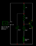
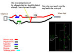
I am working on a project for school show and tell, I found a really cool project that I want to build, it's a magnetic stripe reader made from a mono cassette players magnetic head and uses sound, so there is an amplifer that I am trying to build that will amplify the sound enough to get a reading, so we can scan all our student id's, and I just started getting into electronics, I really love this new world but I'm so lost when reading schematics so if anyone can please help me!! I already have the schematics of different types, then I drew a picture representing how I inturpreted the schematic (how I connected all the wires) there are two pictures here of other peoples designs, I just need something simular to that, I want to be able to make this portable so I can connect in the jack to handheld recorder, then plug in the recorder and remove the sound file from it on the computer and get the information that way, instead of just plugging it into the sound card on a computer, because I dont have a laptop to plug into so I will just take it over to the teachers computer to remove the files and show everyone how it read.
**broken link removed**
http://obrazki.elektroda.pl/57_1306152784.png
http://obrazki.elektroda.pl/40_1306152784.jpg
http://obrazki.elektroda.pl/62_1306152784.jpg
http://obrazki.elektroda.pl/55_1306152784.jpg
 

Hi Andro,

I think you did well in reading the schematic and building your circuit.

The missing point is how we will power this pre-amplifier?
Obviously a voltage or current (from a voltage source via a resistor) is needed at the plug entry because the circuit is an active one (having a transistor for example).

Before going on, do you have an idea on how your circuit could be powered (or if it is already powered perhaps)?

Kerim
 

wow! thank you, I thought I got it nearly 100% wrong, I had no ideal I was on the right track!!! But are you sure it's right? Because I just looked at the schematic I just guessed out it should go, also the transistor the middle pin has nothing connected to it, should I have left it like that? So we need a power source, normally I would plug this into a sound card on the computer but I know if I do that then I don't even need this entire amplifier because the computer will do the job of the amplifier, so I wanted this to be portable and I was thinking of plugging it into a small audio recorder that I got from radio shack as a Christmas present. I already took it apart, it saves audio files to the memory chip on the device and I just plug this recorder in the computer to get the .wav file off it and I put that .wav file into a piece of software I found online that translates the .wav file into readable track 1 2 or 3 format. I set the device to read track 1 because that seems to be where our student information is stored, I got partial reads of my ID but it doesn't work right I think because the signal is not strong enough without this amp.
So can this audio recorder that uses a lethium ion battery work to power the amp? I see on the circuit board where the little audio recording box is, is it ok for me to remove that box with the soldering iron and then just stick the positive and negative wires on the board? Because there is no plug for the jack to go in the recorder. If this recorder wont work as a power source, can we add a lethium ion battery to it? I have some old phone batteries that still work good. Please let me know, thank you for your help!!! I'm excited!!

---------- Post added at 16:46 ---------- Previous post was at 16:44 ----------

Just to make sure you know, I did not actually wire my schematic yet, those pictures are of other peoples work, my drawing is: myscheme.jpg and it's my interpretation of how to wire the schematic. I'm trying to copy what I seen in the other pictures.
 

Just by curiosity, do you think the mic input of your sound card has a small dc output voltage (the value is not important)?
It can be measured by a simple DC voltmeter, though the reading could be zero since many microphones are passive (maganetic).
By the way, the two lines of this pre-amplifier have to carry both DC (for biasing the circuit) and AC (the signal) currents.

Edited:
Since I didn't work with recorder heads, I don't have a sure idea on their signal strength (how many mV maximum they output). When I have to deal with a new device, I usually do some tests before deciding how to insert it in a circuit. And it is also normal that one adjusts its final circuit to get the best performance possible.

Edited:
As an experiment you can power this circuit (in parallel with its plug two wires) using a resistor (470 ohm) and 1.5V battery as a first try. Don't forget the polarity of the battery... The minus should go to the transistor emitter.
 
Last edited:

I did not manage to complete this, because it did not work, then someone told me my schematic was wired wrong! :( so finally someone gave me a block schematic that I could understand, so I'm going to try that, also I was wondering if it's possible to change the size of the capacitor to something larger? I have a 470uF instead of a 470nF, does the capacitor size matter so much? I heard from one of the people who wrote an article on these devices that a larger capacitor is ok, but I don't know if that also means that all the sizes of the other components have to also change in size? Please let me know. Thank you!
 

I don't think your circuit is wrong but it may not be the optimum one in respect to sensitivity (which depends on the characteristics of the recorder head) and its output compatibility with the following amplifier input (ac voltage range for example). But since in the circuit there is a transistor, it needs a current supply (usually from a voltage supply and a resistor for example) to bias its transistor in its linear region so its collector current will amplify linearly its base current generated by the very small ac signal of the recorder head.
In my opinion 470n is good since it is at the base side hence it sees a rather high dynamic input resistance (around 5K though its exact value depends on the transistor bias and its current gain).

For instance, your circuit resembles in a way the 2-wire condenser micro which has also a transistor (likely MOSFET) hence it has to be supplied by a DC current (from a voltage source via a resistor) so that on the same 2 wires an audio signal (about a few mV) is outputted. Did you hear of this type of micro?

Kerim
 

Ok thank you for your reply, and about what you are saying having a power source, I removed the audio male connector head and I took an old digital recorder, took it apart and I found where the microphone input is and removed it from the board, then I put the positive and negative wires and soldered them directly on the board in the same place as the microphone used to be. And I recorded and it works! I just click record then swipe my ID and then stop the recorder and when I play it back I can hear the noise it makes!!! So I am wondering if this audio recorder will act as a power supply, or should I take a small 3.5v lethium ion cell phone battery and connect it at the end of the leads right where the audio jack used to be that I cut off. Or where would I put it?
Please let me know, thank you!!!
 

Do you have a way (like a simple voltmeter) to measure the DC volt on the two wires while you are recording? Only DC.
Please tell me what you will get even if the voltage is zero (but during recording because it is possible that the recorder cuts off this small internal supply when idle).
 

Status
Not open for further replies.

Part and Inventory Search

Welcome to EDABoard.com

Sponsor

Back
Top