Continue to Site

Welcome to EDAboard.com

Welcome to our site! EDAboard.com is an international Electronics Discussion Forum focused on EDA software, circuits, schematics, books, theory, papers, asic, pld, 8051, DSP, Network, RF, Analog Design, PCB, Service Manuals... and a whole lot more! To participate you need to register. Registration is free. Click here to register now.

I need help in my circuit to generate dead time

Status
Not open for further replies.

dor8

Junior Member level 1
Joined
Mar 24, 2014
Messages
15
Helped
0
Reputation
0
Reaction score
0
Trophy points
1
Activity points
114
I have a problem with my circle that the drivers are burned (pin 4 shorter to pin 2) or the drivers are not working properly (HO takes out constant signal regardless of to his entry).
I use in UCC27200 driver.
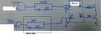
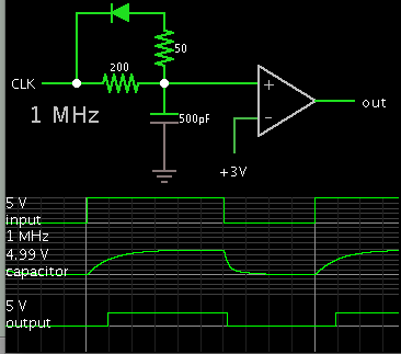
Can some of the problems were caused because I don’t have delay time between switching of the transistors ,So I want to create a circle of delay (Figure 2).
My goal is to create a time delay of a 100n but I need help in calculating the components that would give me the time delay.
And generally how I calculated delay tie in RC Circle?
 

Attachments

  • 1.jpg
    3 MB · Views: 172
  • 2.jpg
    2.jpg
    706.6 KB · Views: 233

RC circuit behaviour follows a simple exponential function. With a threshold voltage of 0.5*Vdd, the delay is 0.7*RC. See https://en.wikipedia.org/wiki/Rc_circuit

Consider a 74HC gate output resistance in a 50 to 100 ohm range, the resistors in your delay circuit should be at least factor 10 larger.
 

The 1nF cap may be drawing excess current from drivers in UCC27700, have RdsOn in the range of 2 to 4 Ohms. You may calc. driver temp. rise from this. Normally gate capacitance can rise this high during transition swing, depending MOSFET specs. Change 30R to 100R or 200R.

Measure all component temp rise. and all gate signals with very short probe tip & ring . <1cm

From what I understand the capacitor can make me a problem?
I just must make a delay- of switching and that the only way I know .
 

Taking SunnySkyGuy's recommendation, and changing the resistance to 200 ohms.

Here is a simulation, showing that by changing the capacitor to 500 pF, you get the desired delay of 100 nSec.

7301073100_1412553607.png


The op amp is not necessary, but it performs as your following device might. Its output changes state when the capacitor transitions above or below 3V.
 
Brad's simulation demonstrates well the asymmetry of delay.

My intent was to use the Ciss of the MOSFET instead which increases rapidly as the Vgs rises above threshold. But this nonlinear capacitance is shown below for an N type from ON Semi.
FET cap.jpg
 

Status
Not open for further replies.

Part and Inventory Search

Welcome to EDABoard.com

Sponsor

Back
Top