Continue to Site

Welcome to EDAboard.com

Welcome to our site! EDAboard.com is an international Electronics Discussion Forum focused on EDA software, circuits, schematics, books, theory, papers, asic, pld, 8051, DSP, Network, RF, Analog Design, PCB, Service Manuals... and a whole lot more! To participate you need to register. Registration is free. Click here to register now.

I Need HELP ASAP With My Electronics Project Please!

Status
Not open for further replies.

Babar Firasat

Newbie level 2
Joined
Apr 5, 2013
Messages
2
Helped
0
Reputation
0
Reaction score
0
Trophy points
1,281
Activity points
1,298
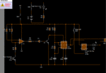
Hi. I am trying to build a laser security system. When the sensor and the transmitter are in range and connected, the buzzer and led are off. But when the connection is cut betweens the sensors, the led and buzzer turns on. When the connection is made again between the sensor and the transmitter, the buzzer turns off and the led stays on, which is switched off by a reset switch. This project seems to work perfectly fine in circuit, but when I simulate it in reality, the circuit doesn't work. Can you help me out please. :) Electronics.gif
 

What simulation software are you using? zip and post your simulation file so that it can be tested. Do you have laser led in the simulator? If yes, place it near the photo-transistor and see if it works.
 

The + input of IC1 is held at +12V

The - input of IC1 will not go higher than +12V, so there is a good change that IC1 output will be permanently high.

I would have put a potentiometer (maybe 100k Ohms) on the + input of IC1 to provide a variable reference voltage.

I am assuming that IC1 is a 741 op-amp or similar?
 

What simulation software are you using? zip and post your simulation file so that it can be tested. Do you have laser led in the simulator? If yes, place it near the photo-transistor and see if it works.


I used circuit wizard 2. You can build this circuit on there in no time.

- - - Updated - - -

The + input of IC1 is held at +12V

The - input of IC1 will not go higher than +12V, so there is a good change that IC1 output will be permanently high.

I would have put a potentiometer (maybe 100k Ohms) on the + input of IC1 to provide a variable reference voltage.

I am assuming that IC1 is a 741 op-amp or similar?


this is my As electronics, i haven't quite understood the basics much. The photo diode is there within the circuit to act as a sensor. in real life, i am using an infra-red transmitter and reciever. the photodiode is there to adjust the lux meaning that in real life, it will act as an object blocking the sensors.

- - - Updated - - -

I used circuit wizard 2. You can build this circuit on there in no time.

- - - Updated - - -


this is my As electronics, i haven't quite understood the basics much. The photo diode is there within the circuit to act as a sensor. in real life, i am using an infra-red transmitter and reciever. the photodiode is there to adjust the lux meaning that in real life, it will act as an object blocking the sensors.

And yes, the op-amp is a 741
 

Status
Not open for further replies.

Similar threads

Part and Inventory Search

Welcome to EDABoard.com

Sponsor

Back
Top