Continue to Site

Welcome to EDAboard.com

Welcome to our site! EDAboard.com is an international Electronics Discussion Forum focused on EDA software, circuits, schematics, books, theory, papers, asic, pld, 8051, DSP, Network, RF, Analog Design, PCB, Service Manuals... and a whole lot more! To participate you need to register. Registration is free. Click here to register now.

I need Fm Transmitter of 1 Watt

Status
Not open for further replies.

arevindh

Junior Member level 1
Joined
Oct 9, 2010
Messages
19
Helped
0
Reputation
0
Reaction score
0
Trophy points
1,281
Location
Aluva, Kerala, India
Activity points
1,406
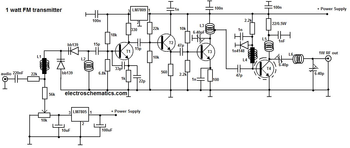
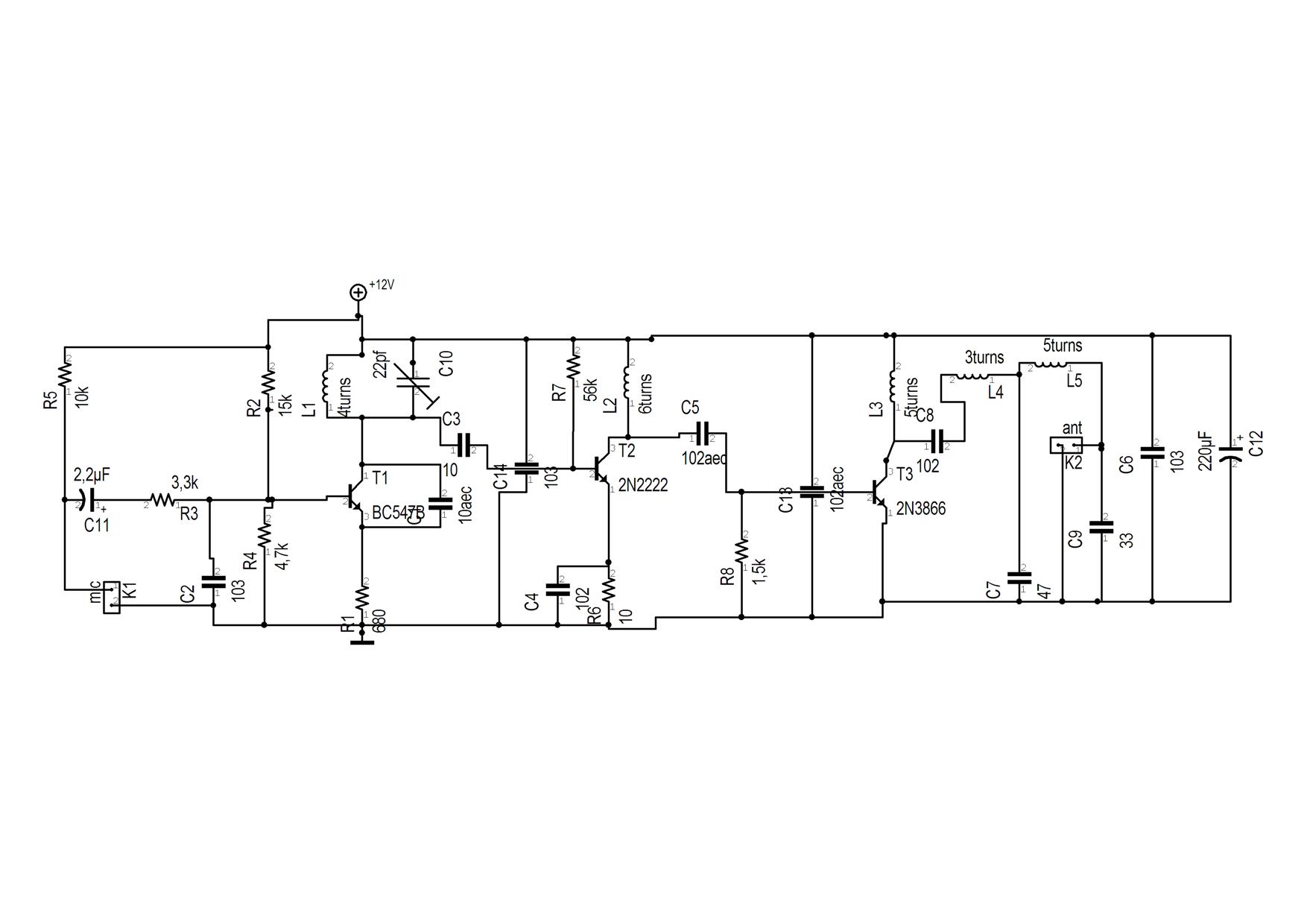
I need Fm Transmitter Circuit :roll:

1.1W o/p power
2.high frequency stability
3.price - low
4.12 v DC supply
 

1 Watt FM Transmitter
50_1286614224.jpg
 
Last edited:
You could derive the tuning voltage, currently taken from the wiper of the potentiometer, from a PLL instead and lock it to a quartz crystal. That would give excellent stability but would need a few more components. If you use the PLL method, be sure the loop filter response is slow enough that it doesn't 'fight' against your modulation voltage. If built properly, the circuit should be fairly stable as it is though. It is a well thought out design and has voltage stabilization where it is needed. You might be able to leave the 5V regulator out and connect the tuning voltage supply to pin 3 of the 9V regulator instead to save a few parts.

Brian.
 

You could derive the tuning voltage, currently taken from the wiper of the potentiometer, from a PLL instead and lock it to a quartz crystal. That would give excellent stability but would need a few more components. If you use the PLL method, be sure the loop filter response is slow enough that it doesn't 'fight' against your modulation voltage. If built properly, the circuit should be fairly stable as it is though. It is a well thought out design and has voltage stabilization where it is needed. You might be able to leave the 5V regulator out and connect the tuning voltage supply to pin 3 of the 9V regulator instead to save a few parts.
Brian.


Friend ,
I tried this with a FM Transmitter bought from a nearest store mfd by " SILICONICS " .But the was a humming voice with transmitted signal. Can I eliminate this ?
 

Friend , I tried this with a FM Transmitter bought from a nearest store mfd by " SILICONICS " .But the was a humming voice with transmitted signal. Can I eliminate this ?
For smooth transmission, ensure that your supply is well filtered or use a battery for better performance. Frequency stability depends highly on the power supply, quality of components used, the material of PCB, and the PCB layout too. Cheers
 

The mod4 fm tx is more reliable and is working fine for me

and frequency u can adjust using variable cap...

or try with vegakit....they have DIY kits available...
 

Attachments

  • fm_transmitter_mod4_pic_schem_181.gif
    fm_transmitter_mod4_pic_schem_181.gif
    115.8 KB · Views: 149

I have attached a file of FM transmitter I bought is PCB Layout by me is also in it (Sorry for the circuit is not well imaged ) It can be opened using Targe3001 V14
 

Attachments

  • fmtrans.zip
    19.6 KB · Views: 119

please upload in pdf format so that every can view it easily boss....

did u try building the mod4 design by audioguru????
 

(Sorry for the circuit is not well imaged ) It can be opened using Targe3001 V14
Always stick to commonly used extensions like JPG, BMP. PDF, TIF, ZiF, RAR etc so that your upload can be viewed and utilised by the needy. OR if you are posting any image from a webpage, just posting the links will be fine.
 

what about this one?
 

Attachments

  • FM88.pdf
    85.5 KB · Views: 140

That should work nicely, even if it is a bit larger and fragile than it could be. It has some nice features, like having the three inductors on different axis. I would place an electrolytic capacitor across the point where power is connected, suggest 100uF, to help with LF stability. Be careful if a heat sink is needed on the output transistor, it could easily touch other parts and the transistor tab is not isolated.

Brian.
 

Always stick to commonly used extensions like JPG, BMP. PDF, TIF, ZiF, RAR etc so that your upload can be viewed and utilised by the needy. OR if you are posting any image from a webpage, just posting the links will be fine.
Given below is the jpg image

:arrow:
Its frequency changes as battery voltage decrease :?:?:?.1 use 8 Rechargeable Ni-Cd Cells to power it can i connect a voltage regulator IC 7806 or 7809 to it ????:-o:-o

---------- Post added at 14:17 ---------- Previous post was at 14:11 ----------

please upload in pdf format so that every can view it easily boss....

did u try building the mod4 design by audioguru????
No i didn't . I have Uploaded jpg image of it pls see it
 

What on Earth was used to draw that !!!

The design has several flaws and I would expect it to change frequency as the supply varied. Look at the earlier schematic and see where the voltage regulators are connected.
I assume from R5 and the lack of pre-emphasis that this is designed to be fed from an electret microphone, is it supposed to be a 'stage microphone' ?

Brian.
 

some good text about RF :)
need some more? glade to help.
 

Attachments

  • TRansmitter Desgin.pdf
    545.9 KB · Views: 134

For all amplifiers / RF circuits / analog circuit, shielding is critical. Companies don't put those things in metal enclosures for no reason!

If you build one of these things and put it in a plastic enclosure, then you deserve to have problems.
 

modification in last posted diagram "FM88"
 

Attachments

  • FM88B.pdf
    59.7 KB · Views: 125

Status
Not open for further replies.

Part and Inventory Search

Welcome to EDABoard.com

Sponsor

Back
Top