Continue to Site

Welcome to EDAboard.com

Welcome to our site! EDAboard.com is an international Electronics Discussion Forum focused on EDA software, circuits, schematics, books, theory, papers, asic, pld, 8051, DSP, Network, RF, Analog Design, PCB, Service Manuals... and a whole lot more! To participate you need to register. Registration is free. Click here to register now.

I have question for chosing right topology for my motor controller

Status
Not open for further replies.

actor23

Member level 3
Member level 3
Joined
Dec 12, 2014
Messages
56
Helped
1
Reputation
2
Reaction score
1
Trophy points
8
Visit site
Activity points
515
Hello all ;

Let me explain my question simple
I designed 3 phase bldc motor driver. I have 48V (Max 55V) Lithium-ion based battery. I need 12V-2A and 5V-0.5 A(maybe lower) two DC output. 12V to feed my gate drivers(TLP250(6)) and 5V to feed my microcontroller. 12V output should share common ground with 48V battery but 5V must be seperate isolated ground.

I examined the push-pull smps but realized that it is used for very high power applications. I think that i choose flyback smps topology which is more efficient and enough power for my design.

My idea is that i designed 48V to 12V flyback or the topology that you suggest me then use optocoupler or optoisolator as dc-dc converter(12 to 5) to feed microcontroller also requirements for isolated ground.

Any ideas,suggestions are really appreciated.

Thanks in advance.
 

Why dont u use buck instead of flyback???

There are two reason why i want to use flyback topology or any switched mode topology.

1) More efficient than buck or boost converter especially flyback does not require external inductor.

2) I need isolation to protect microcontroller so that a transformer must be used.
 

Unregulated DC/DC converters (fixed voltage ratio) are usually made as forward converters. If your converter also implements voltage regulation, flyback can do this without additional energy storage inductors.

The title is misleading because the problem hasn't to do with motor controller function. Rather "converter for isolated mcu supply".
 

Im sorry fwm you are right. I am just seeking the right topology also detailed technical information about which ic should i use or general transformer designing calculaticalculations etc. If you please give me any link or show me the right path for selection components i am very thankful.
 

Re: building boost converter using flyback transformer

I need to design flyback converter as mjasoj but my spesifications are :

Vin= 48-55Vmax (2 Amp or as possibly as low)
Vout1 = 12V-1A
Vout2 = 5V-0.5A(to feed microcontroller maybe lower current)

I want to share information to you also getting some points that i don't know from you so that i post it here.

I don't think use any microcontroller to drive mosfet as you did. Thats why i need complete ic like FSQ series or something like that.(F.e i am thinking using sg3525 or uc2525)

Actually don't know where to start or which equipment or path i should follow.

Waiting your responses, thanks in advance

Regards.
 

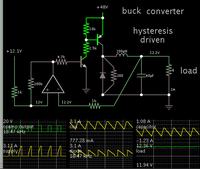
Just for the fun of it, I made a simulation of a simple buck converter. Supply 48V. Output 12V at 2A.

It is self-regulating and uses ordinary components. However it has not been tested in real life.

This shows roughly what kind of waveforms to expect.


The op amp can be powered by an ordinary resistor/zener regulator.

A flyback will draw lower current pulses, but it will still require the same amount of watts.
 

Thanks for the help BradtheRad ;

But, i need seperate isolated supplies. 12V should be share same ground with 48V but 5V must have different ground than others.

The question appeared : if i use any smps that can convert 48V to 12V-2A lets say then use optoisolator like pc817 fed by 12V also proper resistive divider network also zener can i regulate 12V to 5V also get seperated isolated new ground ?

Yes, optoisolator feedback is used frequently to isolate one side from the other.

Question: Do you intend to use the microcontroller to control devices which get the 12V supply? If so then all devices must share a common ground (or a common supply rail, depending). In such a case the flyback (or forward) converter is a better option, to generate both 12V and 5V.
 

My gate drivers are tlp250 they resemble isolation between microcontroller and H-bridge. It is must to connect 12V-gnd to 48V gnd but 5V can be seperated.

You are right bradtherad first, i think of designing push-pull smps but learnt that it is used for high power requirements.The flyback topology make sense but im not still find the way to design flyback. I tried to design using uc3842 in proteus 8 but faced some simulation errors like "uc3842.mdf are not found" I need simulate it firstly in proteus but all attempts are concluded with failure :thumbsdown:

Actually, i need simple and complete application note also usable for proteus
 

You are correct, flyback is the most cost-effective solution. And in DCM mode, cross regulation could be sufficient without any post regulators.

The downside is that flyback's coupled inductor (it is an inductor, not a transformer) is a significant design challenge. But the 48v in, 12v and 5v out arrangement is very common, and perhaps you could find something off the shelf.
 

Since I like to experiment with simulations...

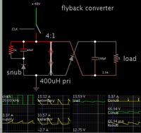
Here is a rudimentary flyback converter, to illustrate the basic concept.

48V in, 13V out at 2.5A.


The switch would be replaced by a mosfet or transistor.

The control is a simple clock driving it at 50% duty cycle. Not shown is a control IC, nor feedback network.

Some kind of snubber network is recommended.
 

Thanks for the design and simulation BradtheRad

but my new concerns are :

1) Why we need auxilary winding on primary side to feed control IC like uc3842,ka3842b or FPS series ?

2) I need aimed design tool. I am using proteus 8 but there are limited transformer model also related control IC ?

Thanks for response of all

Regards.
 

1) Why we need auxilary winding on primary side to feed control IC like uc3842,ka3842b or FPS series ?

The auxiliary winding generates an isolated (and low-voltage) signal, to provide feedback about what is happening in the transformer.

2) I need aimed design tool. I am using proteus 8 but there are limited transformer model also related control IC ?

Falstad's simulator (which I use) does not have these features.

If you try other simulators you may find one that supports more than 2 windings on a transformer. A free and popular one is LTSpice. It contains IC's by Linear Technology. It may have a suitable control IC.
 

I need aimed design tool. I am using proteus 8 but there are limited transformer model also related control IC ?
If you prefer Proteus, it has three windings linear and saturated core transformer models ready-made available, as a SPICE based simulator it would be even able to arbitrary complex models. Where do you see a restriction?
 

Yes,proteus has several transformer options. Unfortunately, it has not control ICs like UC3842 or KA3842 etc but i wiil try LTspice also anyone who has UC3842.mdf or KA3842.mdf (model files) please post to me.

Thanks each of you.

Regards.
 

Status
Not open for further replies.

Similar threads

Part and Inventory Search

Welcome to EDABoard.com

Sponsor

Back
Top