Continue to Site

Welcome to EDAboard.com

Welcome to our site! EDAboard.com is an international Electronics Discussion Forum focused on EDA software, circuits, schematics, books, theory, papers, asic, pld, 8051, DSP, Network, RF, Analog Design, PCB, Service Manuals... and a whole lot more! To participate you need to register. Registration is free. Click here to register now.

hysteresis of capacitor voltage

Status
Not open for further replies.

parth22

Member level 4
Joined
Mar 15, 2022
Messages
78
Helped
2
Reputation
4
Reaction score
1
Trophy points
8
Activity points
518
HI ,
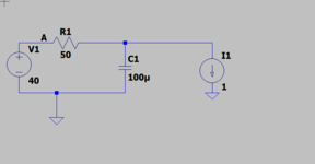
I have a RC circuit, I would like to draw a constant current from capacitor. But i want to draw the current when capacitor is charged around 50%.
Is there any way to make a simulation of this? like by setting a some threshold value or other?
 

Hi,

I don´t understand what you want to do. Please draw a sketch.

Klaus
in the below image,,,there is a constant current load by which i want to draw 1A currnet. but once the capacitor is charged around 60%, then this 1A should start to flow.
one way to make a pulse of this 1A by giving dealy (that can be calculated ,find the time when capacitor is charged upto 60% and i can put but here problem is that capacitor is not charging completely), is there any other way,,,like to make a hysteresis or some kind of reference voltage?
 

Attachments

  • prac2.png
    prac2.png
    5.8 KB · Views: 72

For any case just sim a cap and spec its charge with an initial condition.


Regards, Dana.
 

For any case just sim a cap and spec its charge with an initial condition.


Regards, Dana.
I didn't get it,,can you explain a bit more?
--- Updated ---

For any case just sim a cap and spec its charge with an initial condition.


Regards, Dana.
or any diagram,,,
 
Last edited:

Hi,

Hysteresis is a combination of two thresholds. one for forward, one for back. Or up and down, or ON and OFF.
Currently you just talk about a single threshold. Sadly one time you talk about 50% the other time about 60%.

Then you talk about a pulse. But we don´t know about pulse timing. A single pulse or a pulse train? What frequency?

Then you talk about "%". This is a relative value. We need to know what it is referenced to.
Maybe the input voltage. Maybe 40V.
When we use 40V, then 50% of it is 20V. But is this 40V fix? Or is the inpput voltage variable.
One time the input voltage is 12V, then the thresold becomes 6V.... or 20V --> 10V

Usually when one talks about threshold then a comparator is the device to use. It compares two inputs.

But mind: if you simply use a comparator to switch ON the load current .. then immediately the capacitor voltage will drop and the comparator will immediately switch OFF...then ON, then OFF.

Here is where a true "hysteresis" makes sense.
Maybe ON when capacitor voltage is above 20V .. then staying ON until capacitor voltage drops below 15V, then OFF.

You see there is a lot unclear - at least to me.

--> you have to define more clearly it´s funtion (behaviour) and the threshold(s).

Also draw a simple sketch (timing diagram) where we can see the capacitor voltage and the expected behaviour.

Klaus
 

Is the attached any good to you?.....it is in LTspice
It discharges the cap when its gone down to half of 10v
 

Attachments

  • cap half.zip
    703 bytes · Views: 81

well you have pointed a lot of things.
I present much clear things.
In the below image, I am charging a capacitor ( maximum inrush is 3A allowed, it should be charged in less than 250ms, once cap is charged around 63% of V1 ( it means when Vc1 is reached around 26.46V , then 500mA constant current should start to flow).
Also maximum 2 V drop is allowed across R1, after final charging.
so for constant current drawing, i want to make a hysteresis for the capacitor voltage. or any other way?
--- Updated ---

Is the attached any good to you?.....it is in LTspice
It discharges the cap when its gone down to half of 10v
well I tried as per your suggestion...
can you tell why there is too much voltage drop across R1, can we reduce it (for this we have to reduce R1 but then we will increase inrush so can't reudce R1,,,then what are the ways?
 

Attachments

  • prac2.png
    prac2.png
    36.4 KB · Views: 84
  • prac.zip
    561 bytes · Views: 64
Last edited:

Hi,

to no confuse yourself ( and me) I recommend to change only one parameter.

* now it´s 63%
* now it´s a 3A limit
* not it´s a 15 Ohms resistor.

Also maximum 2 V drop is allowed across R1, after final charging.

use Ohm´s law:
For max 2V drop on a 1A load --> R must not be higher than 2 Ohms.

Klaus
 

Hi,

to no confuse yourself ( and me) I recommend to change only one parameter.

* now it´s 63%
* now it´s a 3A limit
* not it´s a 15 Ohms resistor.


use Ohm´s law:
For max 2V drop on a 1A load --> R must not be higher than 2 Ohms.

Klaus
if you consider maximum R=2 ohm then how much inrush current will flow...if i ma not wrong,,,then it should be 42/2 = 21A,,,and maximum limit is 3A.
so now?
 

It seems to me, (and I’m probably wrong based on the OP‘s inability to clearly and consistently state his objective) that what’s wanted here is a constant current source that’s switched on when the voltage reaches some threshold. A comparator plus a current source would do it, no?
 

It seems to me, (and I’m probably wrong based on the OP‘s inability to clearly and consistently state his objective) that what’s wanted here is a constant current source that’s switched on when the voltage reaches some threshold. A comparator plus a current source would do it, no?
Although I have stated 2 times again,,i don't know you have read these comments or not.
one more time again...for your reference open the post 8, zip file,,,
There i want to draw 500 mA constant current , once the cap is charged around 63% of initial voltage.
here some conditions are there: maximum inrush current allowed is 3A, cap should be charged in less than 200ms.
and after final charging maximum voltage drop allowed at R1 is 2V.
so now ?
 

and maximum limit is 3A.
so now?
It´s a problem of your requirements. They can´t match. At least not with the given circuit.

Although I have stated 2 times again,,i don't know you have read these comments or not.
one more time again...for your reference open the post 8, zip file,,,
There i want to draw 500 mA constant current , once the cap is charged around 63% of initial voltage.
here some conditions are there: maximum inrush current allowed is 3A, cap should be charged in less than 200ms.
and after final charging maximum voltage drop allowed at R1 is 2V.
so now ?
Why that agressive?

For me speaking: on my tablet I can´t open zip files. Maybe others have the same problem.
So I didn´t open the zip file either.

Now again the current changed to 500mA.

Still you did not follow our recommendation to use a comparator in the simulation to control the constant current.

And you did ingore that .. as soon as the load is switched ON the voltage can not rise anymore .. it will tumble around this threshold level randomly .. so what "final charging maximum voltage" are you talking about?

So please don´t blame it on us if the circuit does not work the way you think it should work.

I still miss a clear definiton with the expected timing diagram.

Klaus
 

Although I have stated 2 times again,,i don't know you have read these comments or not.
one more time again...for your reference open the post 8, zip file,,,
There i want to draw 500 mA constant current , once the cap is charged around 63% of initial voltage.
here some conditions are there: maximum inrush current allowed is 3A, cap should be charged in less than 200ms.
and after final charging maximum voltage drop allowed at R1 is 2V.
so now ?
Don't be a jerk.

Nobody here can understand what you're talking about, not to mention the fact that you keep changing things (50%, 60%); and fail to provide answers to the questions that people, who are trying to help you, ask. And I'm reluctant to open a zip file from a belligerent stranger.
 
It´s a problem of your requirements. They can´t match. At least not with the given circuit.


Why that agressive?

For me speaking: on my tablet I can´t open zip files. Maybe others have the same problem.
So I didn´t open the zip file either.

Now again the current changed to 500mA.

Still you did not follow our recommendation to use a comparator in the simulation to control the constant current.

And you did ingore that .. as soon as the load is switched ON the voltage can not rise anymore .. it will tumble around this threshold level randomly .. so what "final charging maximum voltage" are you talking about?

So please don´t blame it on us if the circuit does not work the way you think it should work.

I still miss a clear definiton with the expected timing diagram.

Klaus
Sorry if you feel like that.
This 500mA is current which will drawn by constant current source continuously. While 3A was maximum inrush current that can flow to capacitor.
Btw i got your point...somewhere system requirement is not perfect.
Thanks .
 

.somewhere system requirement is not perfect
An appropriate term is self-contradictory...

A possible solution would be a time-variable current limiting element e.g. a NTC, or a resistor that is bypassed by a relay or electronic switch after capacitor charging.
 

Hi,
This 500mA is current which will drawn by constant current source continuously. While 3A was maximum inrush current that can flow to capacitor.
I already knew that 3A is the inrush current and 0.5A is the constant current.
What I´m talking is: now the constant current is 0.5A but before it was 1A. This has changed (as so many other things).
If the requirement is "just a current between 0.5A and 1A" then a simple resistor could be a fairly good solution.

I just try to support you and give a good solution. But for this I need to understand the requirement.
At first it seemd that 1A is a "true requirement". But when this changes to 0.5A ... it tells me that this was not a true requirement. Thus I tried to find out what function (without referring to your circuit) you really need.

I failed to help because I failed to find out what´s important for you.

Klaus
 

Hi,

I already knew that 3A is the inrush current and 0.5A is the constant current.
What I´m talking is: now the constant current is 0.5A but before it was 1A. This has changed (as so many other things).
If the requirement is "just a current between 0.5A and 1A" then a simple resistor could be a fairly good solution.

I just try to support you and give a good solution. But for this I need to understand the requirement.
At first it seemd that 1A is a "true requirement". But when this changes to 0.5A ... it tells me that this was not a true requirement. Thus I tried to find out what function (without referring to your circuit) you really need.

I failed to help because I failed to find out what´s important for you.

Klau
sorry for such a big confusion. I checked it, it was a mistake.
In the below image, you will find a clear scenario.
My question: is it possible to reduce the voltage drop across (vin , vout)) less than 1V, without changing the inrush current condition (3A), after the final charging.
For me important is not violate the inrush current limit, and as less as voltage drop across R1. otherwise too much heat dissipation by R1.
NOTE: in the behavioral voltage source VC is Vout....so no more confusion.
Also can you suggest or draw the switch configuration at the input side. switch will driven by 3.3V. when switch is on, 42 will come at the Vin. I tried with a npn-pnp configuration, but it is working with capacitor circuit. Normally this switch is working.
can you tell where i am wrong here?
 

Attachments

  • prac2.png
    prac2.png
    43.7 KB · Views: 70
  • prac3.png
    prac3.png
    37.7 KB · Views: 67
Last edited:

Hi,
My question: is it possible to reduce the voltage drop across (vin , vout)) less than 1V, without changing the inrush current condition (3A), after the final charging.
Again: what do you consider as "the final charging" ?
The most basic formula you need to be able to use in electronics is Ohm's law.
And in your case this is the one and only formula you need.

I expect that you to do this on your own.

In post#9 I already did the one calculation for you.

Now the other: for 3A limit on a 40V input the resistance must be higher than 16.7 Ohms.
--> Try to find a resistor with more than 16.7 Ohms but at the same timeless than 2 Ohms.
This is no rocket science. And you really should be able to do this on your own.

And are you aware that your initial question has nothing to do with all this?
And are you aware that we answered your initial question, but you completely ignored our answers?
*********
Take a look back at your thread. Post#1: No information about 3A input current limit, no information about resistor voltage drop.

*****
But we generally don't like to give a short answer like "no, it's impossible".
I wanted to find a solution for your problem. We tried to cooperate with you. We failed in this.

Klaus
 

Status
Not open for further replies.

Similar threads

Part and Inventory Search

Welcome to EDABoard.com

Sponsor

Back
Top