Continue to Site

Welcome to EDAboard.com

Welcome to our site! EDAboard.com is an international Electronics Discussion Forum focused on EDA software, circuits, schematics, books, theory, papers, asic, pld, 8051, DSP, Network, RF, Analog Design, PCB, Service Manuals... and a whole lot more! To participate you need to register. Registration is free. Click here to register now.

HV circuit, current sensing

Status
Not open for further replies.

cdober

Newbie level 2
Joined
Dec 17, 2007
Messages
2
Helped
0
Reputation
0
Reaction score
0
Trophy points
1,281
Activity points
1,302
Hi All,

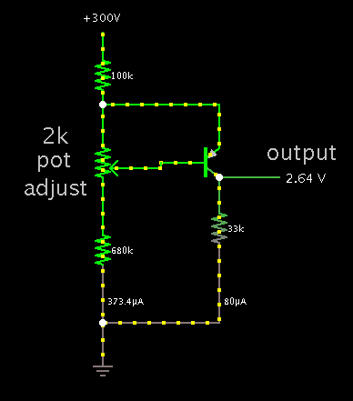
I have a 300v supply which I need to monitor for leakage current. I need to sense >300uA leakage (+/-5%) and produce a low level (2-3v) indication for a microcontroller. Power consumption needs to be under 100uA, and the circuit must be able to withstand a fault (short) at the output of the 300v supply.

Before anyone freaks out about shorting a 300v supply, it's a low level pump circuit charging a 2uF cap :smile: .

I've tried a couple of discrete circuits, but process variations of the components limit accuracy. Integrated solutions give me problems with the fault protection end of things, in that the sensing element develops an instantaneous voltage that will kill the amp.

Any ideas would be most appreciated!

Thanks in advance for your time,

Cliff
 

Put a current monitoring resistor in the earthy end of the supply and connect a pair of diodes across it to limit the voltage under S/C conditions to +- .8V.
Frank

Thanks chuckey, but I'm doing some fairly precise current measurements at the bottom end now. Putting in a low end resistor for leakage detection is going to offset those values and create more headaches...

As far as using diode protection across the sensing element goes, prior experience has shown poor performance in suppressing the instantaneous transient that occurs during a dead short before the diodes can respond. The sensing circuitry usually fails so as to protect the diodes. :)

Cliff
 
Last edited:

Not sure where the detector needs to be located. I get the impression you wish to detect when 300 uA is draining from the 300V source.

This circuit may be backtracking on ground you already covered. If so please disregard.

2276067100_1353964168.png


Not sure where the impedance is, so I installed some resistance at the source, and some at ground.

My detector does not trigger at 300 uA, but the output at the transistor collector will rise to between 2 and 3V when 300 uA is flowing in the left-hand wires.

The detecting transistor itself uses less than 100 uA.
 

if you put in a current sensing resistor, to drop say 10mV at 300 micro amps, then follow it with a X 300 gain op amp, to get 300 micro amps FSD, I can't see the problem. After all 10mV is only .003% of the output voltage.
Frank
 

cdober, here is a solution:
1. Use 3.3K ohm in return path (GND) for current sense.
2. Use 1M ohm and 68K ohm resistors for Voltage devider (68K/1M).
3. Use Analog Devices ADCMP350 low power comparator.
The comparator combines low power feature (10uA supply current) with high input voltage of 22 V and an internal 0.6 volt reference in a low cost package.
I think this configuration will meet all of your requirements.

BEST
 

Status
Not open for further replies.

Part and Inventory Search

Welcome to EDABoard.com

Sponsor

Back
Top