Continue to Site

Welcome to EDAboard.com

Welcome to our site! EDAboard.com is an international Electronics Discussion Forum focused on EDA software, circuits, schematics, books, theory, papers, asic, pld, 8051, DSP, Network, RF, Analog Design, PCB, Service Manuals... and a whole lot more! To participate you need to register. Registration is free. Click here to register now.

ht9200A with the telephone line

Status
Not open for further replies.

foxbrain

Full Member level 2
Joined
Feb 1, 2010
Messages
142
Helped
5
Reputation
10
Reaction score
4
Trophy points
1,298
Location
Damas
Activity points
2,322
hi
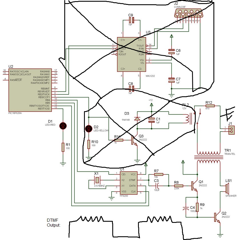
i configured ht9200A with the uC atmega16a and i connected the dtmf output to the phone line directly , the phone line stopped working...
what circuit interface do i need to connect to it? i prefer it without transformers...
thanks
 

What is the datasheet of the transformer (TR1) ?
what is the part from D2 (led-yellow) to the relay 12v used for ?
 

D2 is LE diode (Yellow), and parts right of this diode give device connection to phone line or break it. On J1 connector is connected phone line.

Transformer is standard modem/telephone for isolation with resistance of 600:600.
You can extract some from old modem or any other telephone device.
 
d2 and the right parts : when does it gives a connection or break it?
so can i use a transformer of 100 turns/100 turns ?
and of course i don't need the serial part?
 

You can adjust circuit to your needs and use your uC and firmware, I just post example of connecting HT9200 on phone line, like you ask it in thread question.

- - - Updated - - -

Should be 1:1 ratio but 600:600 ohm 600R is impedance of telephone line. I'm not sure but maybe in US and Canada they have 900R impedance.

Telephone transformer is small and looks like this :

**broken link removed**

- - - Updated - - -

Also see this link with various telephone line interfacing examples :

http://www.epanorama.net/circuits/teleinterface.html
 
i tried and here is the result:
the same sound i hear in the speaker i hear it on the phone but without anything dialed...
so is the problem with the firmware or something else? is there a specific voice i should here from it?
BTW: i didn't put the parts from the relay to D2 and instead i connected the other phone line to ground and the transformer to ground via 470ohm resistor...
 
Last edited:
i tried and here is the result:
the same sound i hear in the speaker i hear it on the phone but without anything dialed...
so is the problem with the firmware or something else? is there a specific voice i should here from it?
BTW: i didn't put the parts from the relay to D2 and instead i connected the other phone line to ground and the transformer to ground via 470ohm resistor...

Post your circuit. Check firmware, probably you have problem in code.

I didnt catch what you try to do ? To dial numbers on phone line ? DTMF, Pulse ?
 

i posted the edited circuit and i draw the dtmf output of the ht9200 in the oscilloscope....
 

Hello Genius,
Greetings to all....I need laneline dialer circuit without use of coupling Transformer...Means expecting good alternative for isolation transformer due to problem of its big sizzzzzzzze...Thanking you in advance
 

Dear sir,
Thanks for your replies.. I would like to transformer specification(datasheet) which used in laneline dialer. Also i need to know the operation of Isolation transformer.. I fully confused by audio signal transmission through isolation transformers..Can you do me favor?

forget to say...In my project i am sending recorded voice to laneline.. how can i merge all the things...8-O8-O8-O8-O
 
Last edited:
Dear sir,
In this circuit Relay used for Pulse dialing DTMF used fo frequency mode dialing.. think i m right...My question is how both are working.. Expecting tutorial about lane line operation...
 

https://www.kentonresearch.co.uk/products/tr01110.htm

- - - Updated - - -

Dear sir,
In this circuit Relay used for Pulse dialing DTMF used fo frequency mode dialing.. think i m right...My question is how both are working.. Expecting tutorial about lane line operation...

Where is circuit what pulse dialing ? :shock:

DTMF and pulse dialing are two different things.

What relay in circuit ?

- - - Updated - - -

Both pulse and DTMF dialing depends from Telecom centrale.
 
Dear Tpetar...
Refer this circuit posted in forum... Relay and dtmf generator IC used here na...But both are separated...Dont know how to pass DTMF signal to telephone signals...

- - - Updated - - -

You only posted that circuit at 07-07-12, 01:25...ht9200A with the telephone line
 

That relay RL2 is small relay for Off-Hook.

I will post you some additional circuit, but its good to use isolation transformer.

See this project, its Alarm with Phone Call:

shema.png

Small relay Off-Hook line when DTMF generator need to send codes (dial predefined number to alert on some event).

Project is located here: https://www.elektronika.ba/505/phone-call-alert/


For pulse dialing see this circuit, its similar as previous, but relay is used to make pulses according to dialing number :

autocall.gif


Also You can see project published in Nuts and Volts, August 2012, called "Alarm AutoDialer" with PIC16F876.

:wink:

- - - Updated - - -

HT9200A is small 8-pin DTMF generator and support only serial connections. HT9200B support serial and parallel. Both have voltage range from 2V to 5,5V.

HT9200A.JPG
 

forget to say...In my project i am sending recorded voice to laneline.. how can i merge all the things...8-O8-O8-O8-O

Just hook audio output with voice to one end of transformer, see circuit examples. Also small reed relay will be useful to make Off-Hook state and activate line, then your uC send recorded audio to line, I supose after dialing some number.

What you mean under "laneline" ?

- - - Updated - - -

Using the HT9200A/B DTMF Generator
**broken link removed**

Here is source code examples for HT9200B in serial and parallel mode, and HT9200A is only for serial mode:

Author of code: BroHogan
Link : **broken link removed**
Link : http://arduinotronics.blogspot.com/2012/11/producing-dtmf-tones.html
Link : **broken link removed**

Parallel Mode

Code:
/* HT9200B DTMF Generator Test                           BroHogan 7/17/09
 * SETUP FOR PARALLEL MODE - Requires 5 pins - 4 data + CS (to stop tone)
 * Serial Mode only req. 2 pins - no CS (cmnd to stop tone)
 * Serial Mode also provides 8 "pure" tones
 * Wire per data sheet - req. 3.57MHz xtal (4.0MHz works but won't dial)
 */

#define D0_PIN  2              // Data 0
#define D1_PIN  3              // Data 1
#define D2_PIN  4              // Data 2
#define D3_PIN  5              // Data 3
#define CS_PIN  6              // Chip Select LOW = On


void setup() {
  pinMode(D0_PIN, OUTPUT);
  pinMode(D1_PIN, OUTPUT);
  pinMode(D2_PIN, OUTPUT);
  pinMode(D3_PIN, OUTPUT);
  pinMode(CS_PIN, OUTPUT);
}

void loop() {
  //DTMF_Out (0,10000);
  //Dial_Phone();
  Test_DTMF();
  delay(1000);
} 

void DTMF_Out (byte digit, long duration){
  digitalWrite(CS_PIN, LOW);           // Enable chip

  digitalWrite(D0_PIN, bitRead(digit,0));
  digitalWrite(D1_PIN, bitRead(digit,1));
  digitalWrite(D2_PIN, bitRead(digit,2));
  digitalWrite(D3_PIN, bitRead(digit,3));
  delay(duration);
  digitalWrite(CS_PIN, HIGH);           // Disable chip (req if parallel)
  delay(100);                           // not required for dialing
}


void Test_DTMF(){  // cycles through all tones
  for (byte i=0; i<16; i++){
    DTMF_Out (i,400);    // use this if parallel
  }
}

void Dial_Phone(){    // dials phone
  DTMF_Out (1,300);
  DTMF_Out (8,300);
  DTMF_Out (0,300);   //SB 10!
  DTMF_Out (0,300);
  DTMF_Out (5,300);
  DTMF_Out (5,300);
  DTMF_Out (5,300);
  DTMF_Out (1,300);
  DTMF_Out (2,300);
  DTMF_Out (1,300);
  DTMF_Out (2,300);
}


Serial Mode

Code:
/* HT9200B DTMF Generator Test                             BroHogan 7/17/09
 * SETUP FOR SERIAL MODE - Requires 3 pins - Data and Clock (100KHz) and CE
 * Wire per data sheet - 3.57MHz xtal (4.0MHz won't dial) S/P to GND = serial
 * Serial Mode also provides 8 "pure" tones (N/A w/ parallel)
 */

#include "HT9200.h"                     // defines for HT9200 DTMF chip
#define DATA_PIN   2                    // Data (serial)
#define CLOCK_PIN  3                    // Clock (serial)
#define CE_PIN     4                    // Chip Enable pin (must control)

#define PHONE_NMBR "18005551212"         // phone # to dial
char PhoneNum[] = PHONE_NMBR;           // load phone # for dialer

void setup() {
  pinMode(DATA_PIN, OUTPUT);
  pinMode(CLOCK_PIN, OUTPUT);
  pinMode(CE_PIN, OUTPUT);
  Init_HT9200();                        // init the chip
}

void loop() {
  Dialer();                             // dials phone
  delay(1000);
  Pure_Tones();                         // plays all the pure tones
  delay(3000);
} 

void Init_HT9200 (){
  digitalWrite(CE_PIN, HIGH);           // start with chip disabled (else you go nuts)
  digitalWrite(CLOCK_PIN, HIGH);        // start with clock pin high
  digitalWrite(CE_PIN, LOW);            // now enable the chip
  delay(10);                            // delay 10ms to ramp up the ocillator
  DTMF_Out (DTMF_OFF,1,0);              // turn off ant tone from previous run
}

void DTMF_Out (byte digit, long duration, long pause){  // FOR SERIAL COMM
  if (digit == 0) digit = 10;           // take care of 0 here
  for (byte i=0; i<5; i++){
    digitalWrite(CLOCK_PIN, HIGH);      // clock high while setting data
    digitalWrite(DATA_PIN, bitRead(digit,i)); // set data LSB->MSB
    delayMicroseconds(5);               // 1/2 of 100K Clock speed
    digitalWrite(CLOCK_PIN, LOW);       // clock low to latch data
    delayMicroseconds(5);               // 1/2 of 100K Clock speed
  }
  delay(duration);                      // how long tone will play
  if (pause != 0){                      // tone sounds continuously if zero
    for (byte i=0; i<5; i++){           // same as above
      digitalWrite(CLOCK_PIN, HIGH);
      digitalWrite(DATA_PIN, bitRead(DTMF_OFF,i));
      delayMicroseconds(5);
      digitalWrite(CLOCK_PIN, LOW);
      delayMicroseconds(5);
    }
    delay(pause);                       // how long pause between tones
  }
}


void Dialer(){  // cycles through all tones
  for (byte i=0; i<11; i++){
    DTMF_Out(PhoneNum[i]-'0',500,100);  // 1/2 sec tome with 1/10 pause
  }
}

void Pure_Tones(){
  DTMF_Out (HZ_697,1000,0);
  DTMF_Out (HZ_770,1000,0);
  DTMF_Out (HZ_852,1000,0);
  DTMF_Out (HZ_941,1000,0);
  DTMF_Out (HZ_1209,1000,0);
  DTMF_Out (HZ_1336,1000,0);
  DTMF_Out (HZ_1477,1000,0);
  DTMF_Out (HZ_1633,1000,0);

  DTMF_Out (DTMF_OFF,1,0);              // turn off DTMF because zero pause used
}


Include file HT9200.H

Code:
/* HT9200.h  defines for HT9200 DTMF chip in serial mode */

#define DTMF_OFF  24  // SB 31 but next cmd will be lost - a not used cmnd# works fine
#define STAR      11
#define POUND     12
#define A_KEY     13
#define B_KEY     14
#define C_KEY     15
#define D_KEY      0

// pure frequencies that can be made by the chip . . .
#define HZ_697    16
#define HZ_770    17
#define HZ_852    18
#define HZ_941    19
#define HZ_1209   20
#define HZ_1336   21
#define HZ_1477   22
#define HZ_1633   23


Video Example

DTMF Genereator and Receiver based on HT9200 IC by Jake's - Jake Sutherland
**broken link removed**


:wink:
 
Last edited:

Dear Genius,
Warm greetings to all. i started to learn PCB designing through Express PCB software..Its so fine for initial level..
My doubt is,While create new component library we don't have any tools for measuring PIN to PIN spacing. Means we cant measure distance as our desired point to point..And more kindly approach me for good professional PCB designing software....


Thanks in Advance dears
 

Dear Genius,
Warm greetings to all. i started to learn PCB designing through Express PCB software..Its so fine for initial level..
My doubt is,While create new component library we don't have any tools for measuring PIN to PIN spacing. Means we cant measure distance as our desired point to point..And more kindly approach me for good professional PCB designing software....
Thanks in Advance dears

Hi Prabhukaran3,

My opinion about creating libraries for starter level of usage is that this is wasting of time. You should use some better software and also easy to use, lets say CadSoft Eagle. There is lots of existing librarires with huge numbers of parts and you need just to start to use it, no need for creating lib parts.
If you want to check real size of part, then print board on paper and compare size with real part. For measuring length or distance use Nonius instrument.

;-)
 

Status
Not open for further replies.

Similar threads

Part and Inventory Search

Welcome to EDABoard.com

Sponsor

Back
Top