Continue to Site

Welcome to EDAboard.com

Welcome to our site! EDAboard.com is an international Electronics Discussion Forum focused on EDA software, circuits, schematics, books, theory, papers, asic, pld, 8051, DSP, Network, RF, Analog Design, PCB, Service Manuals... and a whole lot more! To participate you need to register. Registration is free. Click here to register now.

howland circuit performace problems.

Status
Not open for further replies.

zoulzubazz

Member level 5
Joined
Apr 26, 2012
Messages
87
Helped
3
Reputation
6
Reaction score
3
Trophy points
1,288
Activity points
2,040
Hello guys,

I have designed a howland circuit with 0.01% tolerance resistances (chose resistor from a pack such that their values showed 9963 ohms on multimeter) as shown in the picture. Now the problem is when testing the load bearing capabilities of the circuit the output current decays after about 6.5k ohms which i would like to extend to about 10k ohms. Also in order to achieve the performance i have got now the power supply has to be turned all the way upto +15 to -15 volts which i would ideally like to bring down to about plus,minus 7.5 V. I am trying to push around 800uA through the load which can if there is no other option be lowered upto 400uA. Thanks very much.
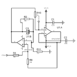
howland.png
 

You didn't manage to describe the observed problem clearly. We just can guess that it's about exceeding guaranteed OP input or output voltage range.

But it's a simple calculation that hasn't much to do with the said Howland circuit. Output current multiply load resistance makes output voltage and must be within the input voltage limits, also the the output voltage of the driving OP, which is higher by the 1k resistor voltage drop, must not exceed the output voltage range.

Reducing the supply voltage to +/- 7.5 V would considerably reduce the output voltage swing.
 
hello FvM, i observed clipping at the output (sinusoidal input) at increased loads, now to run the circuit the output current has been lowered to 250 uA to increase the load range to around 10k ohms and supply voltage to +/- 7.5 V. what changes in the circuit would you recommend so as the circuit provides a steady current in 10 kohms load range? (currently there is a steady degradation of 10 uA). thanks very much.
 

What do you mean by 10 µA degradation? Undistorted sine with reduced magnitude? How do you measure it, what's the frequency?
 

thanks, when measured magnitude is reduced by 10 uA (mesured using a scope, load connected in series with a 100 ohm shunt to measure flowing current). the frequency range of interest is between 1kHz to 100kHz, the same lowering of current is observed at different frequencies in this range. Hope this sheds more light. Thanks again.
 

I didn't notice this before, but C3 will definitely ruinate the dynamic current source characteristic, if it's actually populated.

As another point, with 10k load, the closed loop bandwidth of the circuit is about 220 kHz, so you get a noticeable gain drop at 100 kHz.
 

C3 has not been populated in the circuit. out of curiosity how would one calculate the closed loop BW and other characteristics of this circuit like output impedance? Thanks very much.
 

Status
Not open for further replies.

Similar threads

Part and Inventory Search

Welcome to EDABoard.com

Sponsor

Back
Top