neazoi
Advanced Member level 6
Hello,
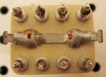
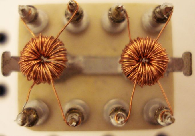
how should I wind the phasing transformers in this schematic?
http://www.neazoi.com/technology/diodes_only/mxr80.htm
They are two toroid cores.
I am confused about the turns direction both on top and bottom
how should I wind the phasing transformers in this schematic?
http://www.neazoi.com/technology/diodes_only/mxr80.htm
They are two toroid cores.
I am confused about the turns direction both on top and bottom
")