Continue to Site

Welcome to EDAboard.com

Welcome to our site! EDAboard.com is an international Electronics Discussion Forum focused on EDA software, circuits, schematics, books, theory, papers, asic, pld, 8051, DSP, Network, RF, Analog Design, PCB, Service Manuals... and a whole lot more! To participate you need to register. Registration is free. Click here to register now.

how to use transformer in circuit maker

Status
Not open for further replies.

shreyas_patel21

Full Member level 3
Joined
Jan 4, 2011
Messages
181
Helped
15
Reputation
30
Reaction score
14
Trophy points
1,298
Activity points
2,325
hello everyone I am using circuit maker software for simulation.

Is there any way to simulate multitap transformer?
there is no component for multitap transformer.
can we make our own component of multitap transformer.?

thank you!
 
Last edited:
I am not familiar with circuit maker but perhaps you let the transformer secondary (or primary) float. If you don't like to ground any node in the floating part of the circuit, you can add a large value resistor (say 10MEG) from one node in it to ground.
If this will not solve your error... then I hope some others will help you soon.
 
thank you KerimF!

it was graound problem.

Is there any way to simulate multitap transformer?
there is no component for multitap transformer.
can we make our own component of multitap transformer.?

thankyou
 

Of course we can. But I am not sure how I can help with the 'circuit maker'.

Edited:
It happens that the first simulator I started with about 1 year ago is LTspice (easy, professional and free :) ).
LTspice allows us to build the circuit as a shematic then simulate it.
How does circuit maker work?... Perhaps it is similar in this respect.
 
Last edited:

yes I found it also works the same but i dont know how to make components in it?

Thank you
 

how do you specify its characteristics? like Lp (primary inductance)... Np/Ns (turn ratio)... K (mutual inductance, usually close to 1)... etc
 

how do you specify its characteristics? like Lp (primary inductance)... Np/Ns (turn ratio)... K (mutual inductance, usually close to 1)... etc

by double clicking on component and putting the values in its properties.
 

Sorry I can't guess which properties of the transformer you can specify, since we work on two different simulators.
 

thank you! I was talking about properties like primary:secondary ratio
 

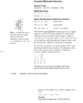
Is it possible to add 2 coils on the schematic and define their coupling coefficient (K)?

Added:
I downloaded now "CircuitMaker User Manual.pdf"
I will try to read it. But it seems it has an example for your question.

I had this PDF by seatching on Yahoo:

"circuit maker" pdf

And I got:
Integrated Schematic Capture and Circuit Simulation
www.wfu.edu/.../CircuitMaker User Manual.pdf Cannot be opened, it is just a reference as given by Yahoo.

Coupled_Inductors.png
 
Last edited:

thank you!

here I found the PDF
**broken link removed**

but
It is not possible to add 2 coils in the scheamtic as you suggested.

but I will try to create new component as per **broken link removed**
 

I couldn't download the PDF you found... perhaps it is our server.
About the 3 coils, I wasn't suggesting but just showing you that "circuit maker" has this function.

Good luck
 
Status
Not open for further replies.

Part and Inventory Search

Welcome to EDABoard.com

Sponsor

Back
Top