Continue to Site

Welcome to EDAboard.com

Welcome to our site! EDAboard.com is an international Electronics Discussion Forum focused on EDA software, circuits, schematics, books, theory, papers, asic, pld, 8051, DSP, Network, RF, Analog Design, PCB, Service Manuals... and a whole lot more! To participate you need to register. Registration is free. Click here to register now.

How to use an MHz oscillator. Capacitor?

Status
Not open for further replies.

TriggerHappy

Junior Member level 3
Joined
Sep 7, 2011
Messages
30
Helped
0
Reputation
0
Reaction score
0
Trophy points
1,286
Activity points
1,706
Seems fairly simple. The Oscillator has 1 output pin. 1 Vdd pin. 1 GND pin.
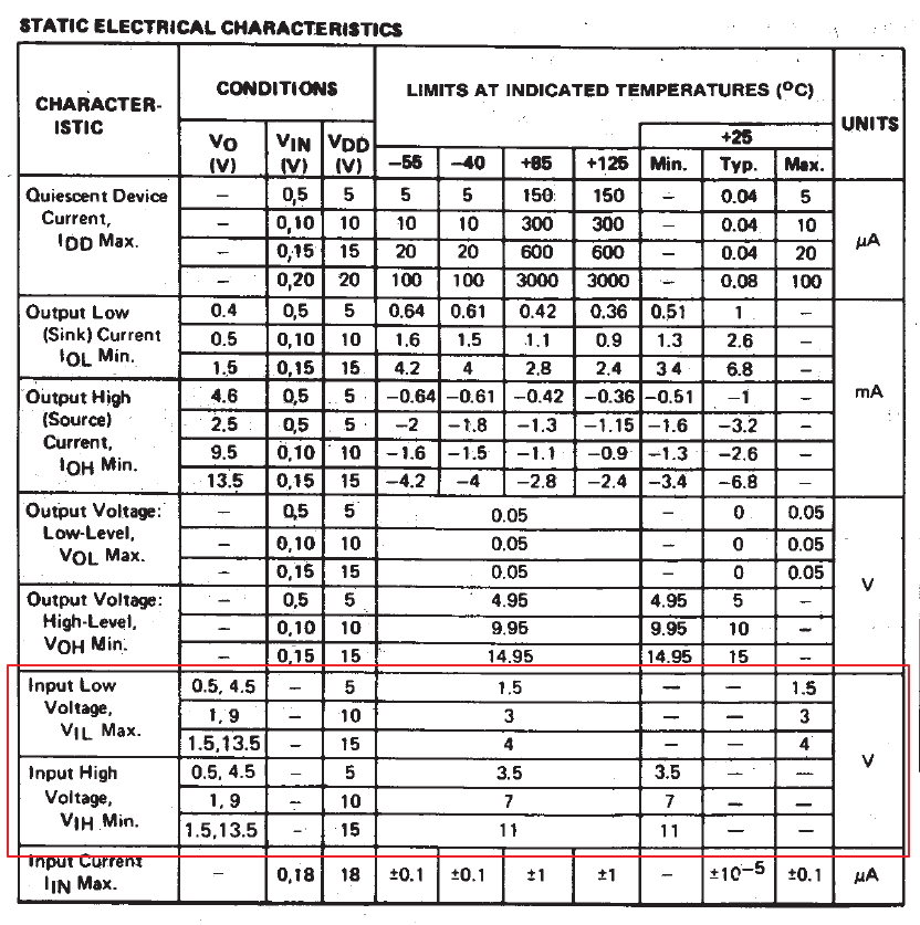
But I can't make it swing. Output is 0v. If it did oscillate, a volt meter would read about 2.5v as in 5v half the time and 0v half the time, right?

Do I need to use a capacitor?
How should I connect it?
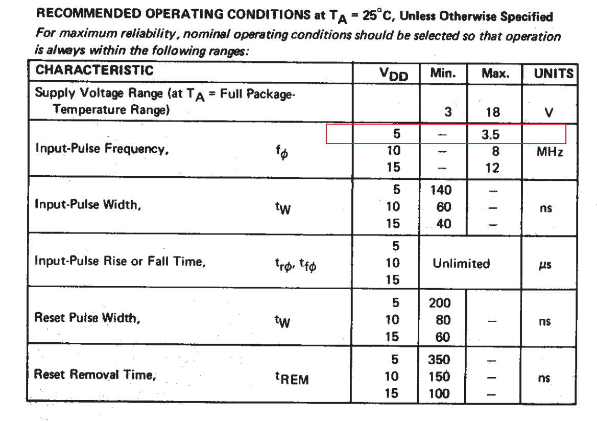
What value should it have? The only two data in this system are 5v and 20 MHz, so what is the formula to determine capacitance?

Once I get the oscillator to... oscillate, I want to connect it to a ripple counter. Is that straight forward between the out pin of the oscillator and the clock pin of the ripple counter?

Oscillator JCO, 20 MHz, 5v
http://www.jauch.de/ablage/med_00000197_1182498208_prd_00000039_en_JCO-5V0.pdf
(I've also tried a 9.8304MHz oscillator with the same result)

Ripple counter CD4020BE
http://www.ti.com/lit/ds/symlink/cd4040b.pdf
 

One thing to check. The oscillator has an optional enable function on pin 1. If your part has this option, the pin must be held in a high state or not connected to anything to enable the output signal. Your observation about a volt meter indicating 2.5V is correct.
 
Your voltmeter can only work to low frequencies, maybe one or two KHz at best. 20MHz is well beyond the capability of most meters. You either need an oscilloscope or something to convert the high frequency to DC so your meter can meaure it. There are two simple methods to try:

1. add a short wire (~10cm) to the output pin and listen on a nearby VHF radio for the 5th harmonic at 100MHZ.
2. add a signal diode (not a power rectifier) to the output pin, anode to the oscillator module, cathode to a capacitor (~100nF) and the other side of the capacitor to the oscillator ground pin. You should then be able to measure a DC voltage across the capacitor.

Brian.
 
Besides the important points mentioned by Brian:

The datasheet of the CD4020B specifies a maximum input-pulse frequency of 3.5MHz with VDD at 5V.

Therefore, both the 20MHz and 9.8304MHz oscillators exceed this specification if the CD4020B is operating with a VDD at 5V.

The 20MHz oscillator still exceeds the specification if the CD4020B is operating with a VDD at 15V.


BigDog
 
Your voltmeter can only work to low frequencies, maybe one or two KHz at best. 20MHz is well beyond the capability of most meters. You either need an oscilloscope or something to convert the high frequency to DC so your meter can meaure it. There are two simple methods to try:

1. add a short wire (~10cm) to the output pin and listen on a nearby VHF radio for the 5th harmonic at 100MHZ.
2. add a signal diode (not a power rectifier) to the output pin, anode to the oscillator module, cathode to a capacitor (~100nF) and the other side of the capacitor to the oscillator ground pin. You should then be able to measure a DC voltage across the capacitor.

Brian.

It works to measure one half the supply voltage on the output of an oscillator with a multimeter set for DC volts. Yes, it is not made for this but I have done it many times with several different meters. An oscilloscope is best but the DC volts measurement is a "quick and dirty" or "go/nogo" check. Try it.
 

Thanks to all of you for your quick and terrific answers!

One thing to check. The oscillator has an optional enable function on pin 1. If your part has this option, the pin must be held in a high state or not connected to anything to enable the output signal. Your observation about a volt meter indicating 2.5V is correct.
YES! It seems it has, because together with the diode+capacitor suggested by Brian, it works when I give 5v to the fourth pin. In the documentation I thought was relevant that pin is labeled "not connected or e/d".

Your voltmeter can only work to low frequencies, maybe one or two KHz at best. 20MHz is well beyond the capability of most meters. You either need an oscilloscope or something to convert the high frequency to DC so your meter can meaure it. There are two simple methods to try:

1. add a short wire (~10cm) to the output pin and listen on a nearby VHF radio for the 5th harmonic at 100MHZ.
2. add a signal diode (not a power rectifier) to the output pin, anode to the oscillator module, cathode to a capacitor (~100nF) and the other side of the capacitor to the oscillator ground pin. You should then be able to measure a DC voltage across the capacitor.

Brian.
I skipped the radio thing for now. I use what I had immediately available, an unlabeled diode and a 33n capacitor, as you describe and the oscillator seems to work. However, the volt meter shows negative -1.4v.

Besides the important points mentioned by Brian:

The datasheet of the CD4020B specifies a maximum input-pulse frequency of 3.5MHz with VDD at 5V.

Therefore, both the 20MHz and 9.8304MHz oscillators exceed this specification if the CD4020B is operating with a VDD at 5V.

The 20MHz oscillator still exceeds the specification if the CD4020B is operating with a VDD at 15V.


BigDog
Indeed!
I have been looking in the datasheet for HEF4020B (not CD4020B) where it says on page 6:
Vdd Min Typ
5 V 5 10 - MHz
10 V 13 25 - MHz
15 V 18 35 - MHz
And I do give the counter 10v, the oscillator 5v.
**broken link removed**

I'll have to get another oscillator or 15v ability to continue. It'll take a few days.

One last thing:
I have LED's connected to the ripple counter which is fed by the oscillator (via a transistor to convert 5v to 10v). The LED's do count at a speed which seems right. But only when I hold my fingers to one of the wires! :-o

If this phenomena persists when I've got the voltage and oscillator frequency matching, what can I do to solve it? Capacitors to the clock pins of the counters? With diodes too?
 

Code:
And I do give the counter 10v, the oscillator 5v
Doesn't work, you have to observe logic level specifications. Why not use fast 74HC4020 with 5V supply?
 

Code:
And I do give the counter 10v, the oscillator 5v
Doesn't work, you have to observe logic level specifications. Why not use fast 74HC4020 with 5V supply?
I use CD4020B because I have them. It can do 12 MHz and that's enough. Even 3.5 MHz would be enough. I just don't have matching components. I will order and wait for a compatible set.

Why couldn't I use 10v for the counters and 5v for the oscillator, with common ground of course? I use two 220v/5v USB-chargers and connect them in series.
Oscillator out to transistor base via 2.2 kOhm, collector to 10v, emitter to counter clock input.
I just might need a capacitor on the 10v too.
 

Why couldn't I use 10v for the counters and 5v for the oscillator, with common ground of course?
Why didn't you read the datasheet, Vih,min = 7V at 10 V Vdd. So you need at least a level translator,
 

As FvM indicated, logic levels must be observed:


With VDD at 10V, VIL = 3V and VIH = 7V, therefore clock pulse of 5V is undefined.

Some method of logic level translation would be required.

I'll leave the discussion concerning the power supply nightmare to others.

BigDog
 

Why didn't you read the datasheet, Vih,min = 7V at 10 V Vdd. So you need at least a level translator,
I use Vdd=Vhi=10v for the counter.
page 3 datasheet says at Vdd=10v, Vhi min = 7v. No typical or max value given.
https://www.ti.com/lit/ds/symlink/cd4040b.pdf

The transistor takes 5v/0v from the oscillator on the base, and 10v through the collector/emittor to the clock pin of the CD4020B. Why wouldn't that work?
 

You are misunderstanding the data sheet. "Vhi min" means the lowest voltage that the device would consider a high logic level. It you are feeding it from an oscillator that runs on a 5V supply the maximum it can possibly provide is 5V so it wouldn't meet the required level.

The reference was to a level translator, not a level transistor! It's just a simple circuit to adapt one level to another. In your case, the simplest would be an NPN transistor and two resistors. Connect the emitter to ground, the base through a 4K7 resistor to the oscillator output and the collector through a 2K2 resistor to the 10V VDD supply. The 5V levels from the oscillator are plenty to turn the transistor on and off like a switch and the collector will then go from 0V to 10V which is what you need for the 4020.

Brian.
 

Status
Not open for further replies.

Similar threads

Part and Inventory Search

Welcome to EDABoard.com

Sponsor

Back
Top