Continue to Site

Welcome to EDAboard.com

Welcome to our site! EDAboard.com is an international Electronics Discussion Forum focused on EDA software, circuits, schematics, books, theory, papers, asic, pld, 8051, DSP, Network, RF, Analog Design, PCB, Service Manuals... and a whole lot more! To participate you need to register. Registration is free. Click here to register now.

How to use a logic gate Mosfet ?

Status
Not open for further replies.

AKENAFAB

Junior Member level 3
Joined
Feb 18, 2007
Messages
26
Helped
6
Reputation
12
Reaction score
6
Trophy points
1,283
Activity points
1,406
Hi

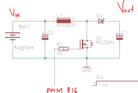
I'm working in a boost converter with pic microcontroller.Boosting 6v to 24v@1W

The power supply for the circuit is a 6.0volts@7AHr SLA battery.

So I decided to use a IRLZ24 mosfet,it's a logic gate mosfet to avoid to add other power supply to mosfet driver and keep a small circuit.

Can i control it using the pwm pin connected directly to gate mosfet ? or Should I use some totem-pole driver ?

The boost circuit is working at 100KHZ but i cant get more tha 100mA :/ :sad:

Any suggestion ?

31_1316216174.jpg


53_1316216174.jpg


ty!
 

How did you calculate the inductance of the coil? What value and kind did you use?

I'm not an expert at this kind of circuits, but it seems to me, that you need a MOSFET driver. Do you have a scope (or at least an ocasional access to one)? You may want to check the voltage at the gate. Does the mosfet heat up? And what is the output to input power ratio? Extraordinary low power efficiency could suggest too long rising and falling times of gate drive signal.

hi , I use the formula for Inductance by Texas Instruments app-note. Im using a 22uH toroid core.12A , and **broken link removed** and a formula from Marty Brown Cookbook , comparing the got it values ,all of them are almost equal.

To fire the gate mosfet I use a push-pull drive , always 5v or 0v.

The mosfet heats up when I change the Rload to a lower value.
----------------------------------------------------------------------
Vin=6volts
Voutput desired = 24v@1A

Now i´ve changed the PWM frecuency to 20KHz the voltage goes up to 20v at 1/2 Load.So I add other mosfet in parallel , I mean , each mosfet has his own gate resistor and shares the Drain connected to the Coil.

The mosfets are cooler than before.

Looks like this mosfet is getting short to this application because if I use only one mosfet it heats up quickly and the voltage can't reach 16v.

Ty!
 
Last edited:

Status
Not open for further replies.

Similar threads

Part and Inventory Search

Welcome to EDABoard.com

Sponsor

Back
Top