Continue to Site

Welcome to EDAboard.com

Welcome to our site! EDAboard.com is an international Electronics Discussion Forum focused on EDA software, circuits, schematics, books, theory, papers, asic, pld, 8051, DSP, Network, RF, Analog Design, PCB, Service Manuals... and a whole lot more! To participate you need to register. Registration is free. Click here to register now.

How to turn on RGB Led (Amber color) with out microcontroller

ragav4456

Full Member level 4
Joined
Aug 1, 2012
Messages
228
Helped
19
Reputation
38
Reaction score
17
Trophy points
1,308
Activity points
2,568
RGB led (Amber color) on and off control with out microcontroller. Is it possible.
Input voltage is 24VDC.
Need to design a circuit when the 24V is received, the LED will turn on (Amber).
Any idea? Please help?
 
Hi,

basically:
If you want the color "amber" from an RGB LED then you need the three currents (R, G, B) to have the correct relation.
Red will be the biggest current, then green and just a bit of blue.

And for "when the 24V is reached" you may use a comparator or a circuit using: zener, bjt, Rs.
Circuits are easy to find with an internet search.

But in detail it depends on
* how much the "24V" vary. Min to max.
* if the "24V" also is the supply for the LEDs, then how "weak" the "24V" is (adding hysteresis to avoid oscillation)
* the overall LED current
* the expected accuracy (Does it need to be ON at 24.001V and OFF at 23.99V?)
* the expected efficiency

My ideas:
If you want "amber" just use an amber LED, not an RGB one.
I don´t like the idea to drive a LED from 24V. Because if LED voltage is about 2.2V you "waste" 21.8V. We don´t know the LED current, but just if you have 50mW at the LED you will waste about 500mW in the current limiters (Rs)

Klaus
 
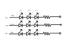
Please check this below circuit. Shall we use transistor or mosfet for this switching.
 

Attachments

  • RGB led.png
    RGB led.png
    9 KB · Views: 93
Hi,

Should I use the train or the airplane to visit my mother?

Without information from your side about current, LED voltage, expected loss, ... and so on .. how can we know?
Without additional information both may be used.

In the above post I took much effort to get informations from you... but got nothing.


Klaus
 
Failure to give adequate information will result in an inadequate answer.

At its simplest, link all the 24V connections together and use it as your positive 24V input. Link the right side of all the resistors together and use it as the negative input. Scale the resistors to get the color you want. We can't tell you the values to use because we don't know anything about the LEDs or how bright they have to be.

Brian.
 
For high currents, say 100's of mA, this is one approach using a LM317
V regulator in constant current mode. Note Zener you have to choose
a higher power zener than one shown. Just calc Pz = Iled x Vz, plus some
margin.

1684663748660.png


For low currents , say 10 - 20 mA,
--- Updated ---

You can replace the LM317 and its R with a constant current diode for
the low current designs :


Regards, Dana.
 
Last edited:
Thanks for your reply.

RGB led part number : 703-1039
R 30mA, G 30mA, B 30mA
R 1.9V, G 3.2V, B 3.2V

I need to achieve amber color, with out microcontroller.
 
Different currents will result in different colors. More current in a LED means it will be brighter within its rated range. When you say 'amber' it doesn't define a particular brightness or hue so it is difficult to tell you exactly what values to use. Generally, amber would be a mix of red, a smaller amount of green with a smaller amount of blue.

I use hundreds of those LEDS and would advise keeping the current well below their maximum rating for best reliability. Try to keep it to no more that 20mA if possible I use PWM to control the output color but that would be complicated if you don't know how that works.

The formula for calculating the resistor values is "(supply voltage - LED Vf) / LED current" where Vf is in Volts, LED current is in Amps and the series resistor value is in Ohms. For example to make the red LED pass 10mA with a 24V supply you would need (24 - 1.9) / 0.01 = 2210 Ohms. In practice, the nearest standard value would be 2.2K (2200 Ohms).

Note that LEDs require a DC supply, if you reverse the voltage across them or use AC they will die.

Brian.
 
This is, based on your desire no processors, complicated approach but
you could design a solution around a color sensor :


Back to processors for a moment, assuming you do not know how to program have
you ever looked at block languages ? Kids in 6'th grade on using this to program robots.

Here is an example where the goal was to use a pot to create a simple V to Pulse Width
converter. Could use it to control a LE brightness or a dc motors speed or....

1685098365916.png


Just took 5 blocks.....

Here used to control a fan speed :

1685099183321.png


Basically you drag out of 2'ond window blocks of functionality into right hand window, config them, like
setting pin number for manipulation or reading, and then hit button to program board / chip. mBlock
converts your block configuration into Arduino code and then programs the board / chip.

A more involved, but still simple, program to do a very sophisticated timer with sequenced operations.
Think of as super 555 timer approach.


mBlock is free, board to start with $ 2 to $ 3, Arduino Nano. Videos online and in Youtube to
get started.....

There are many block languages, here is a more sophisticated design a talking voltmeter
using Snap4Arduino, another block language :


I would posit you have been using a 4 function calculator since you were a kid. Then
you were programming a micro, even though it was not called that. You understood
sequence of operations, operations like mul divide subtract, saving intermediate
values, eg. variable..


Regards, Dana.
 
Last edited:
Hi,

so where exactly is the problem now?

How to get "amber", how to switch ON, how to use Ohm´s law.

Or do you just want others do your job?

Klaus
 
Back to basic problem.

Do you only want amber color out of the RGB groups ? Or will
you need several colors to be generated based on some criteria ?

If former, as previously suggested, just buy a amber LED and
drive it with a switch in series with it in series with an R.

Power >> R >> LED >> Switch >> Ground

If latter describe these additional colors needed and what triggers their
being turned on.


Regards, Dana.
 
Last edited:

LaTeX Commands Quick-Menu:

Part and Inventory Search

Welcome to EDABoard.com

Sponsor

Back
Top