Continue to Site

Welcome to EDAboard.com

Welcome to our site! EDAboard.com is an international Electronics Discussion Forum focused on EDA software, circuits, schematics, books, theory, papers, asic, pld, 8051, DSP, Network, RF, Analog Design, PCB, Service Manuals... and a whole lot more! To participate you need to register. Registration is free. Click here to register now.

how to test a parabolic antenna

Status
Not open for further replies.

vamshi999

Newbie level 5
Joined
Jan 19, 2010
Messages
10
Helped
0
Reputation
0
Reaction score
0
Trophy points
1,281
Location
usa
Activity points
1,349
hi
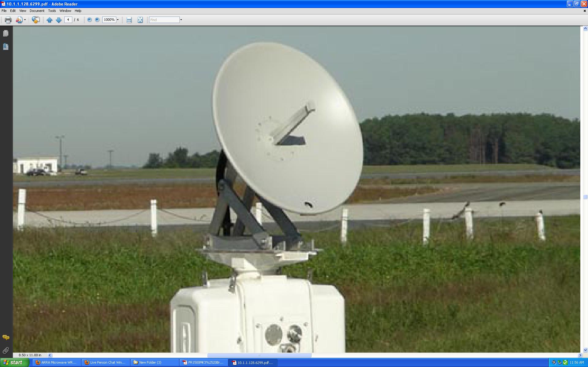
i want to test a parabolic antenna (X-band 9410 MHz) ...... i know there are some software's like HFSS and FEKO but i am a newbie in this area ..can you please tell any easy way to test my antenna

thank you
 

You are not making sense. You do not test an antenna with software. You test an antenna with test equipment.
 

You are not making sense. You do not test an antenna with software. You test an antenna with test equipment.
k sorry ... since i have already told you that i am new to this ....so can you please tell me what kind of test equipment would i need to test it..
thank you
 

You may need an Vector Network Analysis to test S11.

Then you maybe need two standard horn antenna to test your antenna gain, first use one transmitter, one tx horn antenna, one rx horn antenna, one receiver or spectrum analysis to calibrate the chain. Then replace one horn antenna with your antenna to test gain, lobe etc.

PS: You need test in the absorb room, or test in two building top, separated several hundreds meter away, with line-of-sight.
 
Last edited:
Here is a good way to start. You will need a signal source, some sort of power sensor like a spectrum analyzer or a amplifier/power meter. You set the parabolic antenna up outside on a swivel. You set up a horn antenna of some sort, maybe 10 feet away. You point the parabolic antenna directly at the fixed horn antenna, and recorde the spectrum analyzer reading. You then sweep the parabolic antenna in azimuth +/- maybe 45 degrees. You then plot the received power for each 5 degrees increment.

The above is a "relative gain" test, where you are measuring the "directivity of the parabolic antenna. The initial data point, where the parabolic antenna is pointed directly at the horn antenna--most people relable this data point as "zero dB".

The get an absolute gain measurement, such as in dBi readings, you have to temporarily replace the parabolic antenna with another antenna of known gain, and calibrate out the whole system.

---------- Post added at 02:06 AM ---------- Previous post was at 02:03 AM ----------

Sorry, I am a little confused about how to upload a sketch! They have changed the way that works on this forum and I can not get it to work. Here is the URL:

https://obrazki.elektroda.pl/99_1283825106.jpg
 
do we need any software or readings from this test would be enough..?.. if we have to use a software which ones the best..
which software is cheap and good for new users?..
 

Dear Vamshi: All depends on how exact results you need, and what instrumentation you have. First I would recommend to take mechanical measurements on your antenna; the data will show if your antenna shape fits the precision paraboloid, and what the deviations are. If the deviations are larger than 1/8 of the wavelength, then more effort may be not worth of it. If the antenna is mechanically sound, then you have to calculate the focus position, and locate your primary radiator there. It is difficult to determine precisely the "phase center" of the radiator, so make provision to adjust the focus length.
As other colleagues recommended above, you will need a calibrated signal source, and a testing range or an anechoic chamber to measure your antenna gain and pattern. I prefer using the Sun to calibrate my antennas, so I need a sensitive receiver for 9.5 GHz. Its noise figure should be < 10 dB. With an output indicator reading receiver response to solar noise, it takes 1-2 hours to adjust the precise focus and to estimate the side-lobe response.
 

    V

    Points: 2
    Helpful Answer Positive Rating
can we get any parabolic dish and use it for an x-band freq? .. or we have to only buy a x-band dish?..... if the parabolic dish is of a different band, can we just replace the feed with x-band waveguide?.. i have to find a 2ft parabolic dish now.. which works in this frequency .. ..
 

Dear Vamshi:

As I wrote, it depends upon your application. There are many antennas on the market, many made for lower frequencies than your X-band. If you measure their shape and its deviations from an ideal paraboloid, you may find a good one. Often antennas offered as "good for X-band" are poor. In general, an antenna with a poor shape can be used even at X -band but its gain would be lower than you need, or its radiation pattern can be poor, like having high sidelobe level, etc.
All this makes a good X-band antenna costly. Manufacturers who guarantee the specifications must have a test facility to calibrate their products, and this is costly.
What exactly are YOUR specifications?
 

i am thinking of using a 61cm diameter parabolic dish because i need a 4 deg beamwidth. the frequency is 9410+/- 30 MHz x-band. this is for a radar application.

---------- Post added 09-09-2010 at 12:26 AM ---------- Previous post was 09-08-2010 at 10:49 PM ----------

can anyone tell me what type of feed is this.. ?
 

I think this is a "top-hat" feed with a waveguide passing through the parabola center.
If there is a WR-90 or another waveguide usable at your 9.5 GHz band, the antenna may have to be designed for X-band operation.
Then , having the antenna complete as shown in the picture, the only way to test it is to install it on a suitable test range and use an X-band signal generator and receiver to take the radiation pattern measurements. By this test you can see if your antenna has a good main lobe with the width you need, and side lobes suppressed at least by 10 dB (good antennas like that in the picture achieve 13-15 dB down from the main lobe).
A good test range for such test can be a lawn or a flat roof at least 10 meters long, with no metal obstacles on the sides. You should rotate the antenna in horizontal plane to take one pattern, then again with the antenna (or its feed) set to 90 degrees from the first position. As you expect 4 degrees main beam width, you should rotate the antenna by < 1 deg. steps. As the opposite antenna, a small horn or even a dipole can be used (I used a slot antenna with a diode detector for such tests). Good luck!
 

Status
Not open for further replies.

Part and Inventory Search

Welcome to EDABoard.com

Sponsor

Back
Top