bianchi77
Advanced Member level 4
- Joined
- Jun 11, 2009
- Messages
- 1,313
- Helped
- 21
- Reputation
- 44
- Reaction score
- 20
- Trophy points
- 1,318
- Location
- California
- Activity points
- 9,442
Guys,
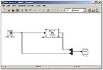
I have created a filter from FDAtool and want to test it on Simulink but I didn't see any response on the Scope
I used discrete impulse as input What can I do to see the output ?
Thanks
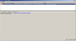
I get this warning :
Warning: The model 'FIRFilterTest' does not have continuous states, hence using the solver 'VariableStepDiscrete' instead of solver 'ode45'. You can disable this diagnostic by explicitly specifying a discrete solver in the solver tab of the Configuration Parameters dialog, or setting 'Automatic solver parameter selection' diagnostic to 'none' in the Diagnostics tab of the Configuration Parameters dialog.
I have created a filter from FDAtool and want to test it on Simulink but I didn't see any response on the Scope
I used discrete impulse as input What can I do to see the output ?
Thanks
I get this warning :
Warning: The model 'FIRFilterTest' does not have continuous states, hence using the solver 'VariableStepDiscrete' instead of solver 'ode45'. You can disable this diagnostic by explicitly specifying a discrete solver in the solver tab of the Configuration Parameters dialog, or setting 'Automatic solver parameter selection' diagnostic to 'none' in the Diagnostics tab of the Configuration Parameters dialog.
Attachments
Last edited: