Continue to Site

Welcome to EDAboard.com

Welcome to our site! EDAboard.com is an international Electronics Discussion Forum focused on EDA software, circuits, schematics, books, theory, papers, asic, pld, 8051, DSP, Network, RF, Analog Design, PCB, Service Manuals... and a whole lot more! To participate you need to register. Registration is free. Click here to register now.

[SOLVED] How to Simulate Skewed (SF, FS, SFA, FSA) Process Corners in Cadence 65nm?

Status
Not open for further replies.

esdeath_123

Junior Member level 3
Joined
Sep 30, 2018
Messages
25
Helped
0
Reputation
0
Reaction score
0
Trophy points
1
Activity points
235
Hi. I have a circuit I'm testing for process variations and I already figured out how to simulate under the TT, SS, FF corners. However, in skewed corners (SF, FS, SFA, FSA), I notice that I seem to be getting weird results. For example,

1. If I click on TT corner (this sets all to typical), then click on SF (some settings are changed to SF, some remain in typical), hit save and run simulations, I get a gain and gbwp.

2. However, if I click on SS corner (setting all to SS), then click on SF (some settings are changed to SF, some remain in SS), hit save and run simulations, I get different gain and gbwp values.

How do I simulate under these skewed corners (SF, FS, SFA, FSA)? Any help or tips would be appreciated.
 

It sounds like a bug. Try to re-start your cadence, the session and your machine. By the way it is possible in Cadence to annotate DC node voltages and operating points from different corners. Maybe that confused you, or try ADE-L. It is not so effective but can eliminate mixed annotations.
 

It sounds like a bug. Try to re-start your cadence, the session and your machine. By the way it is possible in Cadence to annotate DC node voltages and operating points from different corners. Maybe that confused you, or try ADE-L. It is not so effective but can eliminate mixed annotations.

I've tried restarting before I posted the question and the results are still inconsistent. I'm not sure what you mean by annotating DC node voltages? Sorry for the confusion. I forgot to mention that I am only doing AC analysis to get the gain and gbwp so I'm not looking at DC node voltages and operating points, which, if I remember correctly, is only accessible when doing DC Analysis.
 

It sounds like a bug. Try to re-start your cadence, the session and your machine. By the way it is possible in Cadence to annotate DC node voltages and operating points from different corners. Maybe that confused you, or try ADE-L. It is not so effective but can eliminate mixed annotations.

UPDATE: Some follow-up information. I just noticed that some settings (common_poly, common_active, etc.) do not have corners for SF, FS, SFA, or FSA. They only have FF, SS, FFA, SSA, but this is probably the reason why I get different results on the same skewed corner. Given this, which setting should I set this to when simulating under skewed process corners?
 

I think I misunderstood you and I am still confused what is your issue.
Obviously poly resistors won't have FS or SF corners for example, I hope it is clear why not.
And the point of corner simulations to make different situations and see what happens if you combine low supply voltage with slow transistors, fast resistors and high temperature for example.
There is a finite permutation with all the variations and in ADE-XL for any given row in the Corners table you can give multiple values for the same device to enable all the possible variations to run. For example at the row of the transistor you should type in FF FS SF SS next to each other, at the row of the poly resistor type FF SS next to each other and so on.
If not this is your issue could you post a figure about it? I am not sure I see your issue exactly.

11.png12.png
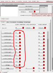
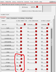
I attached two images. I encircled the settings which do not change at skewed corners (in this case, it remains at TT despite me changing the corner to FS). I repeat my question earlier: since some of these options do not have settings for SF, FS etc, then what do I set them when simulating skewed corners?
 

Aham. When you set FF for example the cadence automatically fill the settings of this window with the data declared in a model.scs file? If yes I would leave them on TT or typ for FS SF corners, default fill should be good.
But actually I have never seen this window before, normally I set corners at the Data view panel which is easy. I would wait for sombody else too to confirm what to do.

I think so, yes. So TT or typ would be good, I take it? And regarding that Data view panel method you mentioned, it's the first I've heard of it. Can you elaborate on how to do this, if you don't mind me asking?
 

I would take it.
Are you using ADE-XL? In ADE-XL when Data view is open on the left side you should find under the tests, parameters, global variables a Corners part. With double click it should pop-up.
(There is a tutorial video how can you use it: https://www.youtube.com/watch?v=bsA2gCgyn6I
With "Import from Tests" button it can automatically read in the model file and the possible corner sections like FF FS SF SS for every device.)

I'm using ADE L. However, I'll definitely check this out since you mentioned this is just easy. Thank you so much! I really appreciate the help :thumbsup:
 

Oh, don't use ADE-L for corner simulations! Point of ADE-XL the easy corner setup, easy monte carlo run and it can save more than 1 simulation results.
If you have ADE-XL license don't hesitate to change for that! Your life will be easier.
You are welcome, and good luck with your stuff!
 
Status
Not open for further replies.

Part and Inventory Search

Welcome to EDABoard.com

Sponsor

Back
Top