Continue to Site

Welcome to EDAboard.com

Welcome to our site! EDAboard.com is an international Electronics Discussion Forum focused on EDA software, circuits, schematics, books, theory, papers, asic, pld, 8051, DSP, Network, RF, Analog Design, PCB, Service Manuals... and a whole lot more! To participate you need to register. Registration is free. Click here to register now.

How to simulate Phase Margin of a opamp with Hspice?

Status
Not open for further replies.

Raymond_di

Newbie level 6
Joined
May 9, 2007
Messages
12
Helped
0
Reputation
0
Reaction score
1
Trophy points
1,281
Activity points
1,337
middlebrook stability analysis

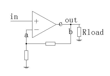
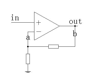
Could any one help me on how to simulate phase margin of a opamp with Hspice?
According to text book, I should break the loop to caculate the loop gain? Where should I break the loop, point A, point B, or any other point? (how to choose the right point to break the loop) How to add stimulation? Then how to calculate the phase margin? Thank you very much!
98_1179816395.jpg
 

spice phase margin

Hi
just measure phse margin of opamp without feedback.
if you want the effect of feedback too you must cut A and measure from A. (input is - of opamp)
regards
 

how to simulate opamp stability

I want the effect of feed back. Do I have to cut A? Could I cut B? If only to break the loop, then what's the rule to choose the point to break it? Thanks

If the circuit is like this:
16_1179885207.jpg
, is it different from the former circuit?

Best Regards!

hr_rezaee said:
Hi
just measure phse margin of opamp without feedback.
if you want the effect of feedback too you must cut A and measure from A. (input is - of opamp)
regards
 

phase margin analysis spice

you need to use large inductor to break the loop from b to a, and need a large capacitor to short a to ground in ac.
 

phase margin hspice

hi

can you pls let me know how can a large inductor break the loop from b to a?

Thanks
 

hspice stability

look for middlebrook stability analysis on google. the best way to do it is shown in that paper. if you do not filn it let me know i will search it in my pc and upload it here.
hock
 

simulate op amp phase margin

Actully, the loop is not broken because you do not want to lose some information about loading effect like capacitance. There is one guy named LvW in this forum who can give you more details about how to break the loop magically. There is another way to simulate the loop named "Striving for small-signal stability" and one guy adapts above paper by using LTspice. There is a book called "The Designer's Guide to SPICE and Spectre" which is useful in ac simulation.
 

    V

    Points: 2
    Helpful Answer Positive Rating
phase margin

Raymond_di said:
I want the effect of feed back. Do I have to cut A? Could I cut B? If only to break the loop, then what's the rule to choose the point to break it? Thanks
If the circuit is like this:........, is it different from the former circuit?
Best Regards!

Hi raymond,

It´s true what was said about the Middlebrook method - however in many cases it is not necessary to apply this somewhat complicated method.
Here are some basics:
1.) You have to break the loop, inject a signal and measure the output at the other "open" point.
2.) This breaking should not change the loading at this point; therefore, the cut should be at a point where a low output impedance sees a high input impedance
(opamp output, for example).
3.) Problem: Due to opamp offset you will most probably loose the operating point which is established by feedback. Therefore, some tricky circuits like the Middlebrook method.
4.) But for relatively simple circuits (like opamp with low output impedance) there is a simple method which is normally sufficient:
Break the loop at the opamp output and inject an AC signal BETWEEN both open ends, that means: not with reference to ground.
5.) Then, the loop gain is the voltage RATIO between those two points.
(The load resistor of your second circuit is not part of the loop but it should be connected if it is present in reality due to its loading effect).
6) This method, normally works good - even until a frequency region where the loop gain approaches unity (for phase margin calculation). For higher frequencies the calculation of the loop gain becomes more and more false.
 
  • Like
Reactions: aandroyd

    V

    Points: 2
    Helpful Answer Positive Rating

    aandroyd

    Points: 2
    Helpful Answer Positive Rating
Status
Not open for further replies.

Part and Inventory Search

Welcome to EDABoard.com

Sponsor

Back
Top