Continue to Site

Welcome to EDAboard.com

Welcome to our site! EDAboard.com is an international Electronics Discussion Forum focused on EDA software, circuits, schematics, books, theory, papers, asic, pld, 8051, DSP, Network, RF, Analog Design, PCB, Service Manuals... and a whole lot more! To participate you need to register. Registration is free. Click here to register now.

how to select acquisition time in A/D?

Status
Not open for further replies.

hemnath

Advanced Member level 3
Joined
Jun 24, 2012
Messages
702
Helped
61
Reputation
120
Reaction score
57
Trophy points
1,308
Location
Chennai
Activity points
6,588
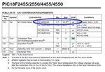
I'm using PIC18F2520 and internal oscillator at 4MHZ.
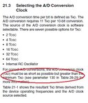
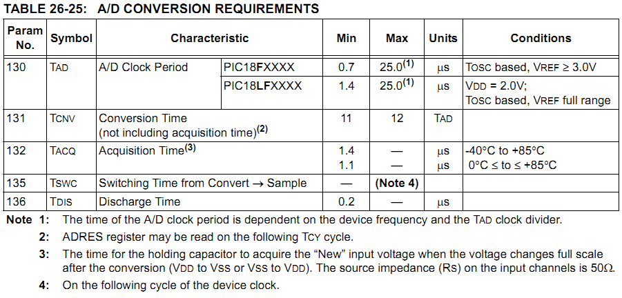
how to select ACQT<2:0> and ADCS<2:0> bits of ADCON2 register.
Fosc = 4MHz . So, Tosc = 1/4Mhz => 0.25us
 

Fosc = 4 Mhz, Tosc = 1/Fosc = 0.25us = 250ns
The A/D conversion time per bit is defined as TAD. The
A/D conversion requires 11 TAD per 10-bit conversion.
The source of the A/D conversion clock is software
selectable. There are seven possible options for TAD:
• 2 TOSC = 0.5us
• 4 TOSC = 1us
• 8 TOSC = 2us
• 16 TOSC = 4us
• 32 TOSC = 8us
• 64 TOSC = 16us
• Internal RC Oscillator
For correct A/D conversions, the A/D conversion clock
(TAD) must be as short as possible but greater than the
minimum TAD (see parameter 130 in Table 28-29 for
more information).
Table 21-1 shows the resultant TAD times derived from
the device operating frequencies and the A/D clock
source selected.

11 TAD is required for 10-bit conversion and 3 TAD is required betwwen conversions do
so 11 + 3 = 14 TAD
So you cannot choose 12 TAD but you can choose 16 TAD

For 16 TAD ACOT2-ACQT0 = 110.
 
thanks for the information. where did you find the information 3TAD is required between conversion . i have loaded for ACQT<2:0> = 110.
for ADCS<2:0> = ???
 

Sorry, Its not 3 TAD between conversions it is 2 TAD.

Page 398 min TAD is mentioned
page 265 TAD per 10-bit conversion
Page 267 2 TAD between Conversions.

Page 263 says 3 TAD is required between conversions.

min TAD = 0.7us

TAD Values

• 2 TOSC = 0.5us
• 4 TOSC = 1us
• 8 TOSC = 2us
• 16 TOSC = 4us
• 32 TOSC = 8us
• 64 TOSC = 16us
• Internal RC Oscillator

So, you cannot use 0.5us. You can use 1us which is greater than the min TAD.

So, you have to use 4 * Tosc = 1us

Fosc/4 = 1/4Tosc = 100 for ADCS2-ADCS0
 

Attachments

  • min tad.jpg
    min tad.jpg
    158.4 KB · Views: 150
  • min tad 2.jpg
    min tad 2.jpg
    68.6 KB · Views: 132
  • tad btwn conv.jpg
    tad btwn conv.jpg
    21.7 KB · Views: 133
  • tad btwn conv 2.jpg
    tad btwn conv 2.jpg
    20.3 KB · Views: 113
Last edited:
on what basis you have calculated min TAD = 0.7us. I don't understand it.
 

It is specified for the PIC. You can find it in the 18F2520 datasheet TABLE 26-25, page 365.

4280280400_1354953413.png


Hope this helps.
Tahmid.
 
i have connected a variable pot to PIN RA5. Vss and Vdd are reference voltage. So ADC value 0 for 0V and 1023 for 5V. But its working like that. What's wrong? and explain please!!!
HTML:
void main()
{
lcd_init(); 				// lcd initialization
TRISA  = 0b00100000;		// RA5 -input, rest as output
ADCON0 = 0b00010000;		// analog channel 4, A/D on
ADCON1 = 0b00001010;		// ref volt. VSS and VDD. AN4 to AN0 as analog
ADCON2 = 0b10110100;		// Right justified, 16 TAD, 1/4Tosc
ADON = 1;
while(1)
{
delay_us(10);   
GO = 1;  					// to start conversion	
while(GO==1);				// wait for bit to be cleared
low_byte = ADRESL;			 
high_byte = ADRESH;
full_value = ((high_byte<<8)|low_byte);
lcd_cmd(0x80);
printf(lcd_data,"%4lu",full_value);
delay_ms(100);
}
}
 

What oscillator frequency are you using? If you are using 20MHz, instead of using FOSC/4, use FOSC/16 or FOSC/64. So, change ADCON2 to either 0b10110101 or 0b10110110.

But its working like that.

You mean, it's not working like expected?

What's wrong?

What output do you get?
 
Last edited:

i tried with ADCON2= 0b10110101..
value in the LCD goes upto the maximum of 255. But not 1023.why is it? is the code is ok?
 

I don't see the declaration of full_value. Did you declare full_value as a 16-bit variable?

Code:
unsigned int full_value;
 

yes i have declared full_value as 16 bit variable. this is my full code. Please help me what i did wrong.
HTML:
#include "18F2520.h"
#include "f2520_regs.h"
#fuses INTRC_IO					// Internal clock
#use delay(clock=4000000) 		// 4MHZ

#define RS PIN_A2  	// LCD RS pin connected to uC PIN_A2
#define EN PIN_A1	// LCD EN pin connected to uC PIN_A1

void lcd_init();
void lcd_cmd(unsigned char);
void lcd_data(unsigned char);

unsigned int8 low_byte,high_byte;
unsigned int16 full_value; 

void main()
{
lcd_init(); 				// lcd initialization
TRISA  = 0b00100000;		// RA5 -input, rest as output
ADCON0 = 0b00010000;		// analog channel 4, A/D on
ADCON1 = 0b00001010;		// ref volt. VSS and VDD. AN4 to AN0 as analog
//ADCON2 = 0b10110100;		// Right justified, 16 TAD, 1/4Tosc
ADCON2 = 0b10110101;       //FOSC/16
ADON = 1;
while(1)
{
delay_us(10);   
GO = 1;  					// to start conversion	
while(GO==1);				// wait for bit to be cleared
low_byte = ADRESL;			 
high_byte = ADRESH;
full_value = ((high_byte<<8)|low_byte);
lcd_cmd(0x80);
printf(lcd_data,"%4lu",full_value);
delay_ms(100);
}
}

void lcd_init()
{
lcd_cmd(0x30);      // Configure the LCD in 8-bit mode, 1 line and 5x7 font
lcd_cmd(0x0c);      // display on and cursor off
lcd_cmd(0x01);      // clear display screen
lcd_cmd(0x06);      // increment cursor
lcd_cmd(0x80);      // set cursor to 1st line
}

void lcd_cmd(unsigned char c)
{
output_b(c);
output_low(RS);
output_high(EN);
delay_ms(15);
output_low(EN);
}

void lcd_data(unsigned char z)
{
output_b(z);
output_high(RS);
output_high(EN);
delay_ms(15);
output_low(EN);
}
 

added the line CMCON = 0x07; .. but still it's not working. rotating the port, and ADC value in the display shows 0 and counts upto 255 and keep rotating, shows 0 and counts upto 255.. it goes on.
 

yes ADCON2 value changed. still the problem remains same.
I can assure that the circuit is fine. I'm using ccs c compiler. I tested with the inbuilt functions in ccs and works perfectly.
why it is not working when i'm using registers?
 

ofcourse. i have changed the value of ADCON2 = 0b10111101; // Right justified, 20 TAD, 1/16Tosc

But its not working. Is this value is correct for TAD 1.2us?
 

When using the library functions, do you get the proper output from 0 to 1023? Do you use the same printf function to print to the LCD then?
 

Status
Not open for further replies.

Similar threads

Part and Inventory Search

Welcome to EDABoard.com

Sponsor

Back
Top