Continue to Site

Welcome to EDAboard.com

Welcome to our site! EDAboard.com is an international Electronics Discussion Forum focused on EDA software, circuits, schematics, books, theory, papers, asic, pld, 8051, DSP, Network, RF, Analog Design, PCB, Service Manuals... and a whole lot more! To participate you need to register. Registration is free. Click here to register now.

[SOLVED] How to read the data from a fifo memory after a certain time?

Status
Not open for further replies.

Cesar0182

Member level 5
Joined
Feb 18, 2019
Messages
85
Helped
0
Reputation
0
Reaction score
0
Trophy points
6
Activity points
825
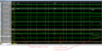
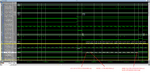
Greetings ... I am currently with a project in ISE 14.5 in which I am implementing the SPI protocol, where I have the 8 bit conversion stage. The 8 bit data is written to the fifo (FIFO Generator 9.3) at a frequency of about 3,125 MHz. But the read frequency is 25 MHz. I want to do is write all my data to the fifo and then read all these data to a frequency 25 MHz from a predetermined read signal, but the problem I am having is that the fifo is automatically reading the data without respecting the read signal that is activated after writing all my data. Someone who can help me control this please. Thanks in advance.
 

Anytime you want help you should always post code.

Can't help you without the code, since your description doesn't tell us anything about how you manage the FIFO read operation.
 

but the problem I am having is that the fifo is automatically reading the data without respecting the read signal that is activated after writing all my data.
Am I correct in interpreting that on the FIFO read side, you get valid data out even when you do not assert the read enable signal, right?

If so, then check whether you have configured the FIFO to be a First Word Fall Through FIFO or not!
 
thanks for the help, it worked for me to change the First Word Fall Through option to Standard FIFO
 

Welcome!
If you design works now, then you may consider to change this thread to Marked as Solved.
 

Although making that change has helped me, I am having some errors in reading some messages. Somehow the last data of some messages are moving to the beginning of the next message as shown in the attached images.

I leave attached the code that I am using.

Code:
wr_ena_data <= '1' when i_spi_rxst = "000" else '0';
spi_rxd_rst_in(7 downto 0)  <= i_spi_rxd;
spi_rxd_rst_in(10 downto 8) <= i_spi_rxst; 

cntr_write : entity work.upcntr generic map (12) -- counter for the number of data written in the fifo of each message
  PORT MAP (
    c   => i_wr_clk,
    ar  => i_rst,
    sr  => wr_en_latch,
    ce  => wr_ena_data,
    q   => cnt_bytes_wr);

cntr_latched : entity work.dreg_clr_sclear generic map(12) -- save the counter value
port map(
    c => i_rd_clk, --i_clk,
    ar => i_rst,
    sc => '0',
    e => rd_ena_latched,
    d => cnt_bytes_wr,
    q => val_cnt_written);

wr_clk_not  <= not i_wr_clk;
wr_ena_fed  : entity work.fed -- falling edge detector to reset the counter of written data
port map(
    c   => wr_clk_not,     -- Clock
    ar  => i_rst,     -- Async active high Reset
    d   => wr_ena_data,     -- D data in
    feu => open,     -- Falling Edge tick, Unregistered
    fec => wr_en_latch      -- Falling Edge tick, Registered
);
rd_clk_not  <= not i_rd_clk;
rd_ena_fed  : entity work.fed -- falling edge detector to start the read data counter.
port map(
    c   => i_rd_clk,     -- Clock
    ar  => i_rst,     -- Async active high Reset
    d   => wr_ena_data,     -- D data in
    feu => open,     -- Falling Edge tick, Unregistered
    fec => rd_ena_latched      -- Falling Edge tick, Registered
);

rd_ena_start : entity work.dreg_clr_sclear generic map(1) -- stays at 1 as long as the counter is less than or equal to the value of written data
port map(
    c => i_rd_clk, --i_clk,
    ar => i_rst,
    sc => clr_rd_latch,
    e => rd_ena_latched,
    d(0) => '1',
    q(0) => rd_en_latch);

cnt_read : entity work.upcntr generic map(12) -- data counter read in each message.
port map(
    c   => i_rd_clk,
    ar  => i_rst,
    sr  => clr_rd_latch,
    ce  => cnt_rd_latched_en,
    q   => cnt_bytes_rd);
cnt_rd_latched_en   <= cnt_rd_latched and rd_en_latch; 
cnt_rd_latched      <= '1' when cnt_bytes_rd <= val_cnt_written else '0';
clr_rd_latch        <= '1' when cnt_bytes_rd > val_cnt_written else '0';

U_spi_data  : l1_coregen_spi_data -- -- FIFO Memory
port map(
    rst         => i_rst,
    wr_clk      => i_wr_clk,
    rd_clk      => i_rd_clk,
    din         => spi_rxd_rst_in,
    wr_en       => wr_ena_data,
    rd_en       => cnt_rd_latched_en,
    dout        => spi_rxd_rst_out,
    full        => open,
    empty       => spi_empty,
    valid       => open,
    rd_data_count => open,
    wr_data_count => open   
);

Could someone please explain why this happens and how can I solve it, if it is clearly observed that the reading signal is correct.
 

Attachments

  • error_fifo_1.png
    error_fifo_1.png
    86.2 KB · Views: 160
  • error_fifo_2.png
    error_fifo_2.png
    97.3 KB · Views: 157

The FIFO is flagged as empty - you can simply ignore this data.
--- Updated ---

This is pretty normal. The internal pointers are probably just reading old data, but the empty flag tells you to ignore it.
 

The FIFO is flagged as empty - you can simply ignore this data.
--- Updated ---

This is pretty normal. The internal pointers are probably just reading old data, but the empty flag tells you to ignore it.
please i need to solve this, how can i control the read data?
 

I suspect it has to do with how you are generating i_wr_clk, i_spi_rxd, and i_spi_rxst. If those come from a testbench, if you aren't generating them off a clocked process you can see these kinds of issues.

What could be happening is the trailing edge of the wr_en is actually not seen by the wr_clk rising edge due to testbench scheduling problems.

One way to check if this is the case, add a signal to the wr_data_count output of the FIFO and verify that it updates in the simulation on the write for 11'h072. My guess is you won't see it update.

If it doesn't update, then do what you should do in all your testbenches use a after delay on all signals (other than clocks) that are inputs to the UUT. I usually throw in a delay of 10% of the clock period to all UUT inputs. I've seen a lot of testbenches that use the opposite edge of the clock to time inputs to a UUT.
 

Thanks for all the help, commenting that I was able to solve the problem, what I did was delay reading the data for a period of the write clock, this after writing the last data.
 
Last edited:

Status
Not open for further replies.

Part and Inventory Search

Welcome to EDABoard.com

Sponsor

Back
Top