debasisswan
Junior Member level 1
Hi,
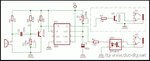
I was looking for a simple sound or light operated switch to trigger my camera flash (For stop action photography) with certain delay between triggering sound or light impulse and final switching- in the range of around 50ms to 500 ms. I found the attached circuit to be simple enough but it cannot provide me time delay between the triggering sound and final switching.
With my limited understating of electronics, I am planning to achieve this delay with certain modification in this circuit. please guide me in this. My idea is- first ii need to keep the pulse width of the 55 very long by rearranging the values of C2 and R3. Next, I will have to make a series of variable resistor (Say R8) and capacitor(say C4). Connect the open resistor end of the series at the point in between R2 and OK1 while connecting the other open capacitor end of the series to ground.
Please guide me- am I correct in my though5t process? if yes, what could be the suggested values for R2, C3, and R8, C4 (the resistor and capacitor to be used in the new series).
Thanks in advance-
Regards-
Debasisswan