Continue to Site

Welcome to EDAboard.com

Welcome to our site! EDAboard.com is an international Electronics Discussion Forum focused on EDA software, circuits, schematics, books, theory, papers, asic, pld, 8051, DSP, Network, RF, Analog Design, PCB, Service Manuals... and a whole lot more! To participate you need to register. Registration is free. Click here to register now.

How to pull up 0-3.3v PWM signal to 0-10v PWM signal??

Status
Not open for further replies.

yzou_ua

Member level 5
Joined
Nov 5, 2008
Messages
92
Helped
1
Reputation
2
Reaction score
1
Trophy points
1,288
Activity points
1,869
I need to amplify the generated PWM signal to 0-10V level. Could someone help me out?? Thx a lot!
 

Just use a transistor with it's collector connected to the 10 volt rail via a resistor.
This will invert the pwm, if thats a problem, use two transistors, an npn and a pnp.
 

#1 - I assume you are sending a logic-type on/off signal right?

#2 - Are you driving a load? If yes, then what type of load?
 

Or use a comparator with the threshold set to ~1.65V (half of 3.3V), maybe add a little hysteresis, say a 1M of 100k resistor. Alternately, you could probably use an op-amp to accomplish the same thing.

**broken link removed**
See also, Google ;-)
 

This chip is very cool because you don't need a bunch of parts, even more cool when you consider the number of parts the dual version would replace. It supports 3.3V and 5V input logic levels, and drive up to 14 Volt. It has a MOSFET, ESD protection, Zener clamps, resistors. Not for people who hate surface mount chips.

ON Semiconductor - NUD3112 - 1 or 2 Relay / Load Driver:
ON Semiconductor NUD3112: 12 V Relay Driver

Datasheet:
https://www.onsemi.com/pub/Collateral/NUD3112-D.PDF
 

Just use a transistor with it's collector connected to the 10 volt rail via a resistor.
This will invert the pwm, if thats a problem, use two transistors, an npn and a pnp.

This is obviously the easiest way and I made it already. But my boss doesn't like it, cuz it induces about 40mv voltage ripple at the switch on/off edges.
So actually, I'm asking a "NO-switch" way... Thx anyway...
 

This is obviously the easiest way and I made it already. But my boss doesn't like it, cuz it induces about 40mv voltage ripple at the switch on/off edges.
So actually, I'm asking a "NO-switch" way... Thx anyway...

I'm not clear on that, you mean a way that doesn't involve any transistor or mosfet switch?
I was about to propose something like https://www.farnell.com/datasheets/85603.pdf but you are obviously searching for something else (non switch) but I'm not sure what it could be.

Alex
 

Assuming you are using a 3V3 Micro, these chips normally have an open collector output pin?
Feed your pwm output into an unused input pin, then translate those levels to your open collector pin, which you have pulled up to 10 Volts.

Job Done!
 

I'm not clear on that, you mean a way that doesn't involve any transistor or mosfet switch?
I was about to propose something like https://www.farnell.com/datasheets/85603.pdf but you are obviously searching for something else (non switch) but I'm not sure what it could be.

Alex

I was thinking op-amp voltage follower stuff, but I'm afraid it is not good idea for high freq. signal, like PWM(16kHz)...

---------- Post added at 19:35 ---------- Previous post was at 19:27 ----------

Assuming you are using a 3V3 Micro, these chips normally have an open collector output pin?
Feed your pwm output into an unused input pin, then translate those levels to your open collector pin, which you have pulled up to 10 Volts.

Job Done!

Could u pls give some details about this, like circ schematics?? Btw, have u done this before, cuz I've never heard about this way... Thx a lot.
 

Assuming you are using a 3V3 Micro, these chips normally have an open collector output pin?
Feed your pwm output into an unused input pin, then translate those levels to your open collector pin, which you have pulled up to 10 Volts.

Job Done!

the PWM is probably generated with the mcu, but using what you say would need a constant polling of the input (where the PWM will be connected) and then transfer this to the output.
Do you think it is a good idea to use the mcu resources in a task like this?

Alex
 

Hopefully, there is a spare input pin with an interrupt.
 

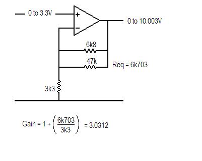
This will do what you want.


33Vto10V.gif
 

Status
Not open for further replies.

Similar threads

Part and Inventory Search

Welcome to EDABoard.com

Sponsor

Back
Top