Continue to Site

Welcome to EDAboard.com

Welcome to our site! EDAboard.com is an international Electronics Discussion Forum focused on EDA software, circuits, schematics, books, theory, papers, asic, pld, 8051, DSP, Network, RF, Analog Design, PCB, Service Manuals... and a whole lot more! To participate you need to register. Registration is free. Click here to register now.

how to protect mosfet 3 phase motor control

Status
Not open for further replies.

abc_de

Full Member level 5
Joined
Jan 9, 2014
Messages
243
Helped
11
Reputation
22
Reaction score
11
Trophy points
1,298
Location
Ludhiana ਪੰਜਾਬ
Activity points
2,939
hello
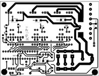
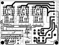
i am using ir2110 as mosfet driver and pic18f2431 microcontoller to drive
3 phase 110vac 2amp motor.
my design is onpen loop no. dc bus monitor and not current feedback.
board is just on off motor. board is working fine from last 1 year.
my problem is some time 2 mosfet shorted 90% half leg may be U/V/W.

how i can protect mosfet to not shorted.
how by monitoring dc bus i can protect. i can not implement current monitor
due to designed pcb.
please help me.
 

Hi,

my guess (that´s all I can do with this little bit of information):
* bad PCB layout --> overvoltage spikes --> destroyed MOSFET isolation barrier --> shorted MOSFET.
* a current monitor will not avoid killing the MOSFETs

A schematic and a PCB layout would be helpful.

Klaus
 

I read many of app notes from infinion also follow their pcb layout technique from notes and demo board etc.
Please let me know how I can show complete pcb layout by gerber file ?
 

Hi,

There are gerber viewers.
You may take photos,
You may use picture export of your PCB software
..

Klaus
 

A BLDC inverter without a current sense is just a plain bad idea.
Especially at eg start up when there is no back emf on the motor coils.
FETs are very bad at breaking high currents...IGBTs are better.

But without current sense?...its like telling a car forum that you want to drive your car without engine oil.
 

Use IGBT's with the highest current rating you can get - put a fast fuse in line with each phase - check the dead time is 500nS under all conditions - make the turn on of the devices slow to limit RFI getting into the control
 

Use IGBT's with the highest current rating you can get - put a fast fuse in line with each phase - check the dead time is 500nS under all conditions - make the turn on of the devices slow to limit RFI getting into the control
Due to cost point of I am using mosfet irf740
Dead time on each leg is 2usec
Fuse is placed on dc bus. It's not always same leg shorted but randomly any leg get shorted.
But it's seen the leg which is very near to dc bus capacitor is shorted very less.
--- Updated ---

A BLDC inverter without a current sense is just a plain bad idea.
Especially at eg start up when there is no back emf on the motor coils.
FETs are very bad at breaking high currents...IGBTs are better.

But without current sense?...its like telling a car forum that you want to drive your car without engine oil.
Sir I am not using bldc motor its acim motor not hall sensor no back emf etc.
Direct pwm by scaler method.
--- Updated ---

a.jpg


Hi,

my guess (that´s all I can do with this little bit of information):
* bad PCB layout --> overvoltage spikes --> destroyed MOSFET isolation barrier --> shorted MOSFET.
* a current monitor will not avoid killing the MOSFETs

A schematic and a PCB layout would be helpful.

Klaus

I request to all please take a look on pcb layout if anything is wrong then let me know.
 

Attachments

  • b.jpg
    b.jpg
    616 KB · Views: 90
  • c.jpg
    c.jpg
    815.4 KB · Views: 93
  • d.jpg
    d.jpg
    437 KB · Views: 99
  • all.PDF
    759.9 KB · Views: 63
Last edited:

What is Ron & Roff on the gate drive?

Are the mosfets properly heatsunk ?

Are there more than 400V at turn off? - across the mosfet's

what is the motor power?

what is the DC bus ? volts? max ?

is the gate drive working properly ?

fast fuses in each motor line seems like a good idea at this stage .....
--- Updated ---

you appear to have no film foil caps across the DC bus right by the mosfets ...? this is a very bad idea not to have any.
 

What is Ron & Roff on the gate drive?
100ohm
Are the mosfets properly heatsunk ?
Yes
Are there more than 400V at turn off? - across the mosfet's
180vdc
what is the motor power?
110vac, 2amp
what is the DC bus ? volts? max ?
180v
is the gate drive working properly ?
everything working fine but mosfet below after few month of regular working
fast fuses in each motor line seems like a good idea at this stage .....
fast fuse only on dc bus +180vdc
--- Updated ---

you appear to have no film foil caps across the DC bus right by the mosfets ...? this is a very bad idea not to have any.
Due to space and cost no decoupling cap on each leg only 470uf/250vdc cap of dc bus


Hi,

PCB layout: doesn't every PCB layout guideline say you need a solid GND plane?
... and fast capacitors?

MOSFET voltage at turn OFF:
Not even a perfect PCB layout will have zero overshot.
And "DC" surely is not correct here. At turn OFF there will be a peak, maybe very short. It's magnitude will vary with load, RPM and other factors.

To refine the question: What is the worst case peak voltage at turn OFF?

The PCB layout does not follow "power switching applicatiin" recommendations.
Please post the PCB layout guideline(s) you used and the demo board PCB layout you talked in post#3 so we can discuss the details.

I still am with my first guess from post#2.

Klaus
 

in India - if you get a surge on the rectified mains, plus the fact you have no local caps on the mosfets means that the odd blow up is to be expected - snubbers across the mosfets would be the only easy attempt at a cure ....
--- Updated ---

what value is C1, C9, etc? what bootstrap diode are you using? what is sw freq?
Actually I am following Germany 🇩🇪 
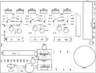
made card to drive motor they also did not add snubber they just add 470uf 250vdc cap their cards a mind blowing even after 10years of regular working no mosfet short all original cards are working excellent.

C1 and c9 are 1nf
Switching frequency is 1.5khz
--- Updated ---


Hi,

PCB layout: doesn't every PCB layout guideline say you need a solid GND plane?
... and fast capacitors?

MOSFET voltage at turn OFF:
Not even a perfect PCB layout will have zero overshot.
And "DC" surely is not correct here. At turn OFF there will be a peak, maybe very short. It's magnitude will vary with load, RPM and other factors.

To refine the question: What is the worst case peak voltage at turn OFF?

The PCB layout does not follow "power switching applicatiin" recommendations.
Please post the PCB layout guideline(s) you used and the demo board PCB layout you talked in post#3 so we can discuss the details.

I still am with my first guess from post#2.

Klaus
I have design it 1.5year ago right now I don't have documents.

But from documents and boards what I have observed that I have implemented
Example: I give different return to each leg and common at fix point make star connection.
Via fuse I give different path of dc to each leg
Driver low side return to mosfet return of respective leg. 10ohm resistor on high side return.
Logic gnd of ir2110 to 7805 not mosfet ground.
Make star connection of 7805 and 7812 and common at single point to dc return.

That's what I have noticed special.

Note:microcontroller and ir2110 never below % is just 5% after years etc. Always mosfet leg shorted or 100ohm gate resistor but 90% only mosfet.

Driver circuit consists
10ohm bootstrap resistor , 3.3uf capacitor Bootstrap capacitor with 18vzener diode.

Gate output 10k pull down ,100gate resistor, 10ohm on side return and diode d15 on each side return connected to respective ground of leg. 1nf capa near gate of mosfet and 18v zener on each gate of mosfet, decoupling on both high side and low side.
22uf capacitor on low side of each driver to feed properly bootstrap cap.
 
Last edited:

Hi,

No documents? Makes no sense, nowadays. I've documents decades of years old. Internet will have, too.

Star connection may be good for low noise, no_current audio circuits.....but for high current switching ... sure you know what you are doing?

Copying boards without understanding of current loops, ground bounce, trace inductivity, ground planes, frequency range of capacitors....
Will result in non reliable design...the long term fail is no surprise.

My recommendation: a PCB redesign.

Klaus
 

    abc_de

    Points: 2
    Helpful Answer Positive Rating
Hi,

No documents? Makes no sense, nowadays. I've documents decades of years old. Internet will have, too.

Star connection may be good for low noise, no_current audio circuits.....but for high current switching ... sure you know what you are doing?

Copying boards without understanding of current loops, ground bounce, trace inductivity, ground planes, frequency range of capacitors....
Will result in non reliable design...the long term fail is no surprise.

My recommendation: a PCB redesign.

Klaus
Ok I got your point may some points are missing due to lack to experience and shortage of time during design time

Then you know about circuit and layout
Then let me know what I have to do for improvement
--- Updated ---

But I have check lot of other pcb which are made in Germany doing same work I think I have good work.
But if something is still missing please let me know
 
Last edited:

Hi,

There are plenty of good application notes and design notes. Read them.
Also in this forum there are many threads where I and others discussed exactly those problems.
Even with bad example layouts and their correction.

Klaus
 

Hi,

There are plenty of good application notes and design notes. Read them.
Also in this forum there are many threads where I and others discussed exactly those problems.
Even with bad example layouts and their correction.

Klaus
Ok
But as per my sense I read and implemented
Give me atleast glue with exact mistake.
Please share your experience
I have not get any help from many posts we just discusse point but no solution even few percent.

Please give mention name of threads name application notes which I am not able to find.
 

Hi,

I´ve already shared my knowledge. Just do a forum search. There are really detailled discussions.
I don´t think I/we need to repeat our knowledge for every member individually. This is not how a forum should work.
Reread post #13.

And read and refer to application notes / design notes. Do your job.

Just saying "I don´t have the documents anymore" is not showing any effort. All information is already available in the internet ... many thousand times.

Klaus
Thanks for suggestions
Now again I will do my job at my own
Read and implement at my own

Strange even experience people did not find single mistake in shown pcb layout with there huge experience
 

AT 1.5KhZ, you should be using IGBT'S ...
--- Updated ---

it appears you have copied a card imperfectly and used slightly different components, possibly lower quality ones, therein lies all the issues.
 

AT 1.5KhZ, you should be using IGBT'S ...
--- Updated ---

it appears you have copied a card imperfectly and used slightly different components, possibly lower quality ones, therein lies all the issues.
I just take the refrence of original pcb it's my own design in original pcb the drive mosfet by transistors and their design is 20year old.
I did software work at my own
I just take the pcb layout refrence from original card but due to different driver circuit their pcb layout did not match with my pcb.

For components point of view I am not sure about quality.

Due to cost I can not use igbt
 

Status
Not open for further replies.

Similar threads

Part and Inventory Search

Welcome to EDABoard.com

Sponsor

Back
Top