Continue to Site

Welcome to EDAboard.com

Welcome to our site! EDAboard.com is an international Electronics Discussion Forum focused on EDA software, circuits, schematics, books, theory, papers, asic, pld, 8051, DSP, Network, RF, Analog Design, PCB, Service Manuals... and a whole lot more! To participate you need to register. Registration is free. Click here to register now.

how to plot Vin Vs Vout curve in cadence.

Status
Not open for further replies.

muffassir

Member level 3
Joined
Sep 15, 2011
Messages
67
Helped
10
Reputation
20
Reaction score
10
Trophy points
1,288
Location
Planet Earth
Activity points
1,802
hi alll,

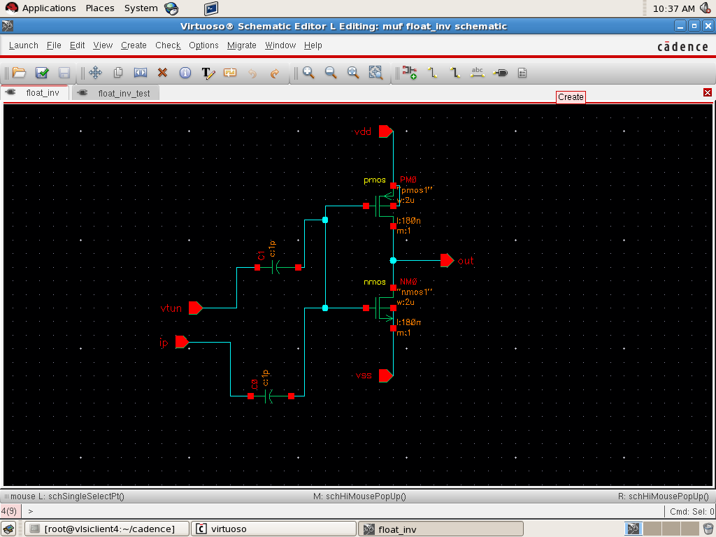
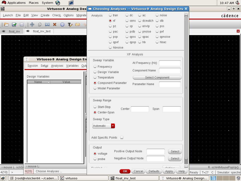
i want to plot the Vin voltage vs Vout curve in cadence ADE L .my circuit is having capacitances at the input ..so i am unable to get it through DC analysis..How can i plot the above curve.

thanks in advance!!!!
 

hi...
dont know about cadance but in spice it can be plot using command .print
 

i want to plot the Vin voltage vs Vout curve in cadence ADE L . How can i plot the above curve.
Run a TF analysis, which will give you Vout/Vin. Or a std. AC analysis, then use ADE's calculator to plot Vin/Vout .
 

Run a TF analysis, which will give you Vout/Vin. Or a std. AC analysis, then use ADE's calculator to plot Vin/Vout .

Hi Erikl ,
Thanks for ur reply,

Here below is my schematics(in gpdk180nm tech process with both the mos of same size) attached.
Here ip is input pin for inverter.vtun is the input pin for giving the tunneling voltage for the tunneling of electrons through the floating gate.
Capacitors used have the value of 1pF each at the input.


Please refer the below attached test schematics.
The input to the inverter is the Pulse voltage of v1=0 and v2=1.8V .the Total time period=20ns,tr=tf=1ns


I dont know what and which fields to filled by what value in the TF analysis..If u elaborate and help me with the values it will be appreciable.

below is the attched empty form of the TF analysis...the same problem i am getting with the AC analysis...Please help me out.


... below is the attched empty form of the TF analysis...the same problem i am getting with the AC analysis...Please help me out.
Currently I have no access to C@dence ADE, sorry. Use the std. help docu!

For ac and xf analyses use Frequency as Sweep Variable, for the Sweep Range use Start-Stop and type in your lower resp. higher frequency limits. The Output should be clear, I think.
 

Status
Not open for further replies.

Part and Inventory Search

Welcome to EDABoard.com

Sponsor

Back
Top