Continue to Site

Welcome to EDAboard.com

Welcome to our site! EDAboard.com is an international Electronics Discussion Forum focused on EDA software, circuits, schematics, books, theory, papers, asic, pld, 8051, DSP, Network, RF, Analog Design, PCB, Service Manuals... and a whole lot more! To participate you need to register. Registration is free. Click here to register now.

how to plot output impedance in HSPICE?

Status
Not open for further replies.

renguo

Newbie level 6
Joined
Oct 30, 2012
Messages
14
Helped
1
Reputation
2
Reaction score
1
Trophy points
1,283
Activity points
1,416
hello,

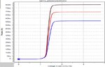
I'm simulating a wilson current mirror and would like to plot the output impedance of the circuit. In theory, it should be as easy as Vout/Iout but I just don't have any idea how to implement it. I know it's possible because I've seen the work of my senior but I can't ask him now. Here's his plot:
2.jpg

Here's my netlist:
Code:
m1 	vd1	vg1	gnd	gnd nch w=5u l=2u
m2	vg1	vg1	gnd	gnd nch w=5u l=2u
m3	vd3	vd1	vg1	gnd nch w=20u l=2u
**********************************************
vdd	vdd	gnd	3.3
iref	vdd	vd1	100uA
r1	vdd	vd3	3k	
**********************************************
.plot dc gm=lx7(m3)
.dc 	vdd	0	3.3	0.1
.print i(m3)

.end
 

Attachments

  • 1.jpg
    1.jpg
    103.2 KB · Views: 238
Last edited:

Replace r1 by a huge inductance L1, inject a unit ac current between vd3 & gnd, and run an .ac simulation with a fixed frequency and a sweep of your vdd. Then plot the voltage on vd3 vs. vdd , its value should represent the output impedance.

I'm not acquainted with HSPICE, but something like this should do it:
Code:
m1 	vd1	vg1	gnd	gnd nch w=5u  l=2u
m2	vg1	vg1	gnd	gnd nch w=5u  l=2u
m3	vd3	vd1	vg1	gnd nch w=20u l=2u
**********************************************
vdd	vdd	gnd	3.3
iref	vdd	vd1	100uA
* r1	vdd	vd3	3k
L1	vdd	vd3	1kH
Iac     vd3     gnd     1A	
**********************************************
.ac 1Meg sweep	vdd	0	3.3	0.1
.plot v(vd3)

.end
 

Thanks for the help! I haven't tried your code yet as I decided to proceed with other homework but I did find a solution in the equation builder of SPICE explorer, which is to plot Vout/Iout. Sheesh, that was easy! However, I'm wondering why your method needs inductor replacement of the resistor. Also, the ac simulation is for the small signal resistance, right? I'm not sure what would be the difference if I just get the DC. Sorry, i'm such a noob :(
 

... the ac simulation is for the small signal resistance, right?
Right!

I'm not sure what would be the difference if I just get the DC.
In the triode region there's not much difference. In the saturation region, however, there will be a big difference: the small signal impedance is much larger than the DC resistance, and relatively independent of Vds, which is not the case for Vout/Iout, of course.
 
  • Like
Reactions: renguo

    renguo

    Points: 2
    Helpful Answer Positive Rating
Hi renguo can you share the solution with me? I have the same problem with hspice 2008..
 

I did not add anything on the netlist. I just used SPICE explorer to plot the graph. Use the Equation Builder under Tools button and put Vout/Iout
 
Last edited:
Status
Not open for further replies.

Part and Inventory Search

Welcome to EDABoard.com

Sponsor

Back
Top