Continue to Site

Welcome to EDAboard.com

Welcome to our site! EDAboard.com is an international Electronics Discussion Forum focused on EDA software, circuits, schematics, books, theory, papers, asic, pld, 8051, DSP, Network, RF, Analog Design, PCB, Service Manuals... and a whole lot more! To participate you need to register. Registration is free. Click here to register now.

how to model differential equations to electronic circuits ?

Status
Not open for further replies.

revooridinesh

Member level 1
Joined
May 31, 2010
Messages
41
Helped
0
Reputation
0
Reaction score
0
Trophy points
1,286
Location
Canada
Activity points
1,553
Hi

Anybody know any material which contains how to model differential equations to electronic circuit ?

Thank You
 

can you be more specific? Differential equations are used widely in all corners electronics..
 

Hi
Anybody know any material which contains how to model differential equations to electronic circuit ?
Thank You
I suppose you mean "how to build electronic circuits that are able to solve diff. equations"? Like an "analog calculator" - a very important tool before the digital computer took over?
Answer: It is best to transfer the diff. equations into integral equations and then to use integrating opamps.
 

In olden times they used analog computers, but now it's all digital, of course. A program such as Mathcad can solve most of the differential equations found in electronic circuits.
 

In olden times they used analog computers, but now it's all digital, of course. A program such as Mathcad can solve most of the differential equations found in electronic circuits.

Yes - however, for my opinion the questioner intends to MODEL differential equations using electronic parts (resp. the corresponding models) as contained in circuit simulation packages.
This can be done with each of the available programs and also with block-oriented simulation programs (as used for control systems)
 

@LvW ya I want to convert those differential equations in to electronic circuit.
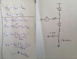
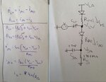
The following image has the equations and the circuit which I converted it to.I simulated the equations in MATLAB and circuit in pspice , but the results are not matching. Which part of my circuit could be wrong ?

upload.JPG
 

@LvW ya I want to convert those differential equations in to electronic circuit.
The following image has the equations and the circuit which I converted it to.I simulated the equations in MATLAB and circuit in pspice , but the results are not matching. Which part of my circuit could be wrong ?
View attachment 84299

Where is the diff. equation?
More than that, the relationship between the drawing and the formulas is missing.
 

extremely sorry for not mentioning the details
the first 2 equations are differential eqns r8 ? d(Q)- differentiation of charge
In the equations Q is charge I current V-voltage. SMi and SAo are valves like structure , SMi = 1 when VLa>Vlv; 0 -else SA0=1 for VLV>VSA; 0 -else
So I realized those IMi and IAo equations each by a Diode and a resistance. CLV is a variable capacitance. VLA is a contant value. Used the voltage source V inorder to drive the circuit , when the top diode in below figure becomes reverse biased.

upload.JPG
 

Capacitor CLV is arranged to act as a differentiator of whatever is in series. This includes whatever is coming from the voltage source V, in conjunction with action through the rest of the network.

Capacitor CSA is arranged to act as an integrator of whatever signal is going across its upper terminal.

I'm not sure if this is what you were looking for.
 

@BradtheRad Thank you for the reply
yeah you are right , but i am looking for the defect in the circuit corresponding to the equations

@LvW Thank you
I am using the ideal diodes for the pspice simulation I guess non-linearities wont come in to existence right ?

Happy New Year :)
 

but i am looking for the defect in the circuit corresponding to the equations

Here is a simple arrangement where a capacitor acts as a differentiator. It's the classic example of course.

Screenshot:

9961538600_1356974911.png


The output voltage shows the rate of change of the source waveform. This is the same as current through the capacitor.

Examples of other ways to use it may not be so obvious.

One issue with your schematic may be with the diodes. The differentiating capacitor must be able to both charge and discharge, in order to show positive and negative values. This means current must be able to flow both ways through the cap. The diodes look as though they interfere with this.
 

we have opamp circuits that have differentiator and integrator manner. you can use that in separate blocks.
 

@LvW Thank you
I am using the ideal diodes for the pspice simulation I guess non-linearities wont come in to existence right ?

Ideal diodes without any non-linearity? Did you find it in the PSpice library?


@LvW yaa the current through it in terms of saturation current, exponential function. I thought other then that one as that was a default one.

then how to model those 2 current equations. I am not supposed to use op-amps(no ICs has to be used only discrete components)
 

Can you build an op amp using discrete transistors? or will that be overkill?

I agree with LvW the Diodes are non-linear and will create problems for you when modeling the equations.

try to incorporate what BradtheRad showed you. are you familiar with laplace?

A very popular circuit,an RLC Tank, has a parallel (or Series) combination of a resistor, capacitor, and inductor.
for a parallel implementation. by changing the voltage, you can solve for current going into each branch by applying differential equations. maybe this will give you a model for what you are trying to do

wikipedia gives a good discussion about this https://en.wikipedia.org/wiki/RLC_circuit
 

Attachments

  • tank.bmp
    527 KB · Views: 94

Status
Not open for further replies.

Part and Inventory Search

Welcome to EDABoard.com

Sponsor

Back
Top