Ohioan
Newbie
We received a video detector from someone, and she asked us if we knew how to measure the VSWR of it.
It's a little thing, with an SMA connector on each end.
I am not an RF engineer, but I do have a little bit of experience in the area. (I did microwave engineering as a co-op student many centuries ago.) So I asked a few RF engineers how to do it, and, well... they didn't seem to know, either.
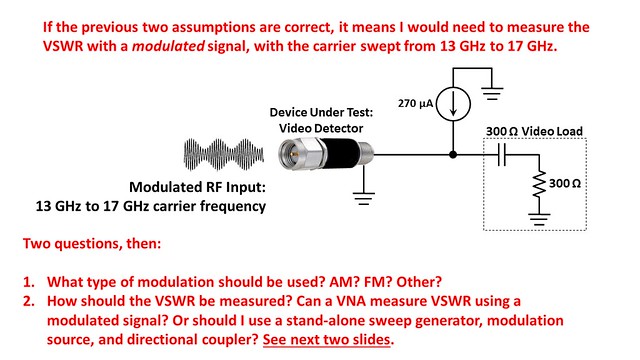
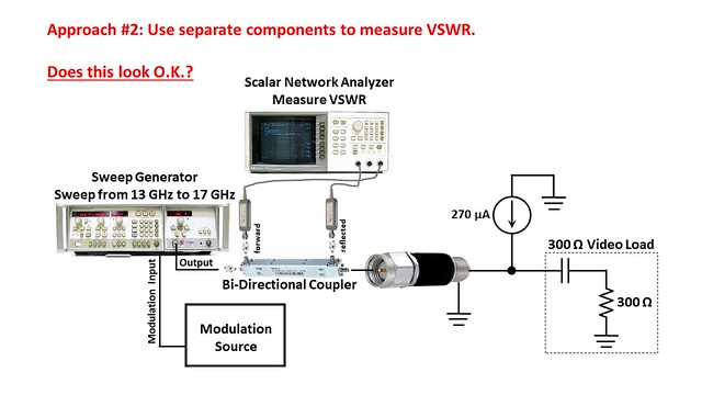
Unfortunately I don't think it's as simple as connecting it to a VNA and measuring the VSWR. The spec says there must be a 300 Ω "video load" connected to the output, and the video detector must be powered using a constant current source. Which I think means I need to measure the VSWR using a modulated signal.
The best way to describe the problem is with some images. I put together some PP slides. Attached is a pdf of the slides. I have also linked to png images of the slides.
Any help/guidance/assistance you can provide would be much appreciated.
Thank you


It's a little thing, with an SMA connector on each end.
I am not an RF engineer, but I do have a little bit of experience in the area. (I did microwave engineering as a co-op student many centuries ago.) So I asked a few RF engineers how to do it, and, well... they didn't seem to know, either.
Unfortunately I don't think it's as simple as connecting it to a VNA and measuring the VSWR. The spec says there must be a 300 Ω "video load" connected to the output, and the video detector must be powered using a constant current source. Which I think means I need to measure the VSWR using a modulated signal.
The best way to describe the problem is with some images. I put together some PP slides. Attached is a pdf of the slides. I have also linked to png images of the slides.
Any help/guidance/assistance you can provide would be much appreciated.
Thank you