tongkin
Newbie level 4
Greetings,
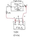
I would like to measure the frequency response of TIA using Frequency Response Analyzer. How to make a connection?
My connection is in the attachment, but it does not work. Normally, my design should have 114dB, but the measurement only show -28dB
Anyone help me please...
Thank you,
I would like to measure the frequency response of TIA using Frequency Response Analyzer. How to make a connection?
My connection is in the attachment, but it does not work. Normally, my design should have 114dB, but the measurement only show -28dB
Anyone help me please...
Thank you,