Continue to Site

Welcome to EDAboard.com

Welcome to our site! EDAboard.com is an international Electronics Discussion Forum focused on EDA software, circuits, schematics, books, theory, papers, asic, pld, 8051, DSP, Network, RF, Analog Design, PCB, Service Manuals... and a whole lot more! To participate you need to register. Registration is free. Click here to register now.

how to measure current in the TIA

Status
Not open for further replies.

timedate

Member level 5
Joined
Jun 20, 2010
Messages
81
Helped
0
Reputation
0
Reaction score
0
Trophy points
1,286
Location
germany
Activity points
1,952
For example, I have two feedback TIAs (with photodiode connected). I want choose the one with large input current signal, and the shunt down the other.

So, I have to measure the average current through the TIA, by means of measure the received optical power.

Does anybody know how to perform this function ? put a ADC connected to the TIA?

Thanks in advance.
 

Most simulators can measure the current through any component. If not, you could insert a 0Ω-resistor or a 0V-vdc which by default measure and show the current through them.


Thanks, but I mean the real circuit, not the simulation. Any hints?
 

Hi,

you want to know the current through the diode?

It is output_voltage / feedback_resistor.
The feedback resistor should be known, the output voltage too, so it is simple math.

Or I misunderstood....?

Klaus
 

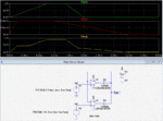
Below is the LTspice simulation of a simple two op amp Analog Max. Value circuit, which should have a smaller output glitch when the output goes from one input to the other as compared to a comparator/analog switch circuit.
It's output is the maximum of the two inputs.

What is the maximum frequency of the inputs?

Max Value Ckt.GIF
 

Status
Not open for further replies.

Part and Inventory Search

Welcome to EDABoard.com

Sponsor

Back
Top