Continue to Site

Welcome to EDAboard.com

Welcome to our site! EDAboard.com is an international Electronics Discussion Forum focused on EDA software, circuits, schematics, books, theory, papers, asic, pld, 8051, DSP, Network, RF, Analog Design, PCB, Service Manuals... and a whole lot more! To participate you need to register. Registration is free. Click here to register now.

how to measure capacitor on pcb

Status
Not open for further replies.

aredhel_vlsi

Member level 4
Joined
Aug 21, 2009
Messages
72
Helped
1
Reputation
2
Reaction score
1
Trophy points
1,288
Activity points
2,013
Hello, I have the following question please. How can I measure the capacitor on a pcb? I have a keysight digital multimeter and I select the capacitance symbol. However, for some capacitors, the indication seems blank. I see mF and it seems like it's waiting for ever to show a value. I tried with the power on and off. Maybe it is damaged? I read on the web that if it is damaged, usually it shows a very big value, far from what is expected. What I am doing wrong? Thank you in advance.
 

Hi,

I found measuring capacitors on board (with the power disconnected and turning on power switch 2 to 3 times to try to discharge the caps) pretty hit and miss, I think it's not a recommended method, some read the right value, some show what you say (mF), even when in good condition - possibly due to how they're wired and connect to other components on the board, seems a bit of a flailing around blindly in a dark room method, so there must be a better technique.
Maybe if the board function and component interaction is known, then suspect capacitor(s) could be removed and replaced (one at a time) [shoddy shotgun method!]. Can doubted capacitor(s) be jumpered out of circuit/bypassed to see if circuit works, or is(/are) capacitor(s) necessary to circuit operation?

I don't remember where, but there are a few websites dedicated to repairing pcbs, TVs, radios (i.e. communications betwen sites, not a little FM hand-held one), etc. that show ways of testing capacitors. I do remember some just say to de-solder, then measure capacitance.

How to check a capacitor which is soldered on a circuit board using digital multimeter? - maybe of use, last three lines of the article a bit confusing, given the title 'though...

How to troubleshoot resistors and capacitors in circuit? , haven't read whole page of replies, last reply says to disconnect one leg/pin and measure R or C, not so practical for SMD capacitor.
 

- - - Updated - - -

Thank you very much for your reply. What I don't understand is why some capacitors on the pcb show the correct value, while others show nothing. How is that possible? You see there is an issue to remove all of them. We talk about 60 caps at least here...And I don't trust I can resolder them properly again, we talk about smd technology.

Well all this came from another issue. I noticed very huge spikes in the output of my voltage regulator (Should be 3.3 V but if I put the plug of the power supply on the laptop) I see 20V peak-to peak, huge overshoot, and also half are negative values. Maybe that's why some pcbs are damaged, it's not only one. So I suspect that the designer of the pcb make a mistake. According to this https://www.digikey.com/en/articles/techzone/2012/apr/protecting-inputs-in-digital-electronics

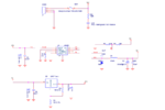
I could avoid the spikes 1) if I add a bigger load (resistor) , or 2) a bigger cap. I m not sure where to start and loose time, so at least I checked the caps in the voltage regulator. What do you think? Below you see my power supply power.PNG

Please note that the regulator is LM1086 and R3 =120 Ohms and R4 =200 Ohms, schematics updated.
 

LCR meter are not designed to measure in circuit. It may be possible under specific circumstances, but it needs good understanding of electronic circuits and instrument parameters to decide where it's the case.

I noticed very huge spikes in the output of my voltage regulator (Should be 3.3 V but if I put the plug of the power supply on the laptop) I see 20V peak-to peak, huge overshoot, and also half are negative values.

You didn't report how you measured the "very huge spike". It's rather easy to see voltage spikes with an oscilloscope that are just measurement artefacts and not actually present in the circuit.
 

- - - Updated - - -

Thank you very much for your reply. What I don't understand is why some capacitors on the pcb show the correct value, while others show nothing. How is that possible? You see there is an issue to remove all of them. We talk about 60 caps at least here...And I don't trust I can resolder them properly again, we talk about smd technology.

Well all this came from another issue. I noticed very huge spikes in the output of my voltage regulator (Should be 3.3 V but if I put the plug of the power supply on the laptop) I see 20V peak-to peak, huge overshoot, and also half are negative values. Maybe that's why some pcbs are damaged, it's not only one. So I suspect that the designer of the pcb make a mistake. According to this https://www.digikey.com/en/articles/techzone/2012/apr/protecting-inputs-in-digital-electronics

I could avoid the spikes 1) if I add a bigger load (resistor) , or 2) a bigger cap. I m not sure where to start and loose time, so at least I checked the caps in the voltage regulator. What do you think? Below you see my power supply View attachment 135913

Please note that the regulator is LM1086 and R3 =120 Ohms and R4 =200 Ohms, schematics updated.

The problem could be because of an alternate path which might be in parallel, so it is not necessary that every capacitor shows you the exact value.
I guess this is the reason why looking for a value when soldered is not preffered.
If u get a proper solution please do post.
Good Luck...
 

Ok thank you for your reply. I will remove then the components and I will try to measure them.

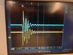
How I measured the spike: The input of the pcb that connects to the usb port has 4 pins: vdd, Data-, Data+, GND. On the Vdd I measure the spike. Also see in attached the image the blue is the vout of the voltage regulator, significantly affected. Oscilloscope is the only way I know to capture the signal, and the instrument I have available. If not like this, how differently? IMG_2162.JPG
 
  • Like
Reactions: FvM

    FvM

    Points: 2
    Helpful Answer Positive Rating
Status
Not open for further replies.

Part and Inventory Search

Welcome to EDABoard.com

Sponsor

Back
Top