YUV
Advanced Member level 4
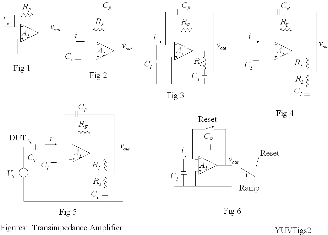
capacitor leakage current
I would like to measure some specific capacitor's parameters like leakage currents or an insulation resistance that might cause those currents. How to measure them properly?
I would like to measure some specific capacitor's parameters like leakage currents or an insulation resistance that might cause those currents. How to measure them properly?