Continue to Site

Welcome to EDAboard.com

Welcome to our site! EDAboard.com is an international Electronics Discussion Forum focused on EDA software, circuits, schematics, books, theory, papers, asic, pld, 8051, DSP, Network, RF, Analog Design, PCB, Service Manuals... and a whole lot more! To participate you need to register. Registration is free. Click here to register now.

How to make ideal OTA(Gm) in candence ? ^^

Status
Not open for further replies.

yixiusky

Member level 2
Joined
May 8, 2008
Messages
46
Helped
0
Reputation
0
Reaction score
0
Trophy points
1,286
Location
Korea
Activity points
1,618
ideal cmfb

hello, i would like to ask one question:

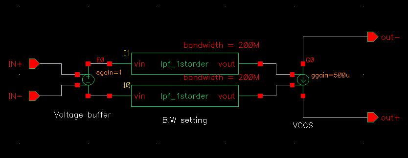
We can make ideal opamp in cadence by using VCVS (in analog library)+lpf_1storder(in ahdl library). VCVS set the gain of Opamp, and the lpf_1storder can set the unity gain bandwidth of Opamp. then we can get ideal Opamp to simulate.

My question is here: I want to get ideal OTA to simulate OTA-C filter. I choose VCCS in analog library to simulate, but i can not get result, and i can not set the bandwidth of OTA also.

So how can we get ideal OTA in cadence ?

Thank you very much ^^
 

ota cadence

Sure, you can use a voltage buffer+lpf to set the BW of your OTA of unity gain, then cascade the VCCS after the lpf.
 
ota gm

thank u very much ^^ do u mean like this ?
 

spectre vccs

Yes, in practical single-ended version of low pass filter is sufficient as long as you keep outputs of VCCS floating as differential outputs.

You probally need another ideal CMFB (balun in spectre) circuit to bias your output common mode voltage
 
gmin in cadence ota

thank you for your reply ^^ i would like to make clear, since i couldn't got your ideal clearly ^^

(1) in practical single-ended version of low pass filter is sufficient as long as you keep outputs of VCCS floating as differential outputs.

Question: what's the meaning of "single-ended version of low pass filter is sufficient "? And if i make outputs of VCCS is grounded, is it ok? That is single-ended OTA, not differential OTA.

(2) You probally need another ideal CMFB (balun in spectre) circuit to bias your output common mode voltage

Question: I put my ideal CMFB in the picture, but where should I add this one based on your opinion ? output of VCCS?

Do u mean it is same as Opamp design? I also should add CMFB to the OTA design ?

Thank you very much ^^
49_1211978743.jpg
[/img]
 

ota bandwidth

yixiusky said:
thank you for your reply ^^ i would like to make clear, since i couldn't got your ideal clearly ^^

(1) in practical single-ended version of low pass filter is sufficient as long as you keep outputs of VCCS floating as differential outputs.

Question: what's the meaning of "single-ended version of low pass filter is sufficient "? And if i make outputs of VCCS is grounded, is it ok? That is single-ended OTA, not differential OTA.

QS: I saw in your previous message that you use 2 low pass filters to filter the internel "differential" voltage. What I mean is that you are right about doing that, but that's not necessary to maintain differential signaling in internal fictitious nodes.

(2) You probally need another ideal CMFB (balun in spectre) circuit to bias your output common mode voltage

Question: I put my ideal CMFB in the picture, but where should I add this one based on your opinion ? output of VCCS?

Do u mean it is same as Opamp design? I also should add CMFB to the OTA design ?

QS: you can attach your CMFB outputs to inputs of 2 additional common mode VCCS that regulates the common mode of differential outputs to the wanted voltage as long as this high gain loop make your simulator happy to converge.


Thank you very much ^^
49_1211978743.jpg
[/img]
 

    yixiusky

    Points: 2
    Helpful Answer Positive Rating
ideal ota

thank u very much ^^ got it. To make sure, i add the picture use only 1 lpf, is it right based on ur opinion ? but if i only use 1 lpf, how can I set one of the differential inputs to VCCS as shown in picture ^^ thank u very much ^^
 

ideal ota in cadence

yes, simply attach it to the gnd because the output voltage of lpf is also referenced to gnd.
you are welcome.
 

    yixiusky

    Points: 2
    Helpful Answer Positive Rating
vccs ota

Thank u very much, i am totally clear now ^^

I have last two quesitons, I am sorry :D

(1) When we design OTA (Gm) for the OTA-C filter, we must make sure the phase margin of OTA is equal to 90 degree, right ?

(2) I would like to know the detail design process for OTA-C filter, could u recommon book or material ?

Thank you very much ^^
 

spectre operational transconductance amplifier

(1) usually 60 degree across PVT corners is sufficient, 90 degree seems to be overdesigned
(2) you can refer to Willy Sansen's "analog deisng esstential", there is a whole chapter on analog filters. It can be found in this forum.
 

    yixiusky

    Points: 2
    Helpful Answer Positive Rating
Status
Not open for further replies.

Similar threads

Part and Inventory Search

Welcome to EDABoard.com

Sponsor

Back
Top