Continue to Site

Welcome to EDAboard.com

Welcome to our site! EDAboard.com is an international Electronics Discussion Forum focused on EDA software, circuits, schematics, books, theory, papers, asic, pld, 8051, DSP, Network, RF, Analog Design, PCB, Service Manuals... and a whole lot more! To participate you need to register. Registration is free. Click here to register now.

How to make a Worldclock generator with randomely altered frequency around 96KHz?

Status
Not open for further replies.

FlorianB

Newbie level 4
Newbie level 4
Joined
Dec 30, 2013
Messages
7
Helped
0
Reputation
0
Reaction score
0
Trophy points
1
Location
Santa Monica, CA
florianbador.com
Activity points
88
How to make a Worldclock generator with randomly altered frequency around 96KHz?

Hi!

For a very specific project of mine I would need to create a hardware worldclock generator (BNC).
The frequency would be around 96KHz, and very stable from one impulse to the next, but the frequency itself would vary "randomly" around 96KHz at a 100-500ms rate.

I would have 3 buttons:
- amplitude of variation (e.g. 1% would allow the frequency to vary from 95.04 to 96.96)
- average speed of variation
- amplitude of speed
But these 3 are still pretty "random".

We can basically summarize this project as a "tape pitch" simulator for soundcards / audio DA converters.

Anyone knows where I could start my research?

THANKS!
 

I've never heard the term 'Worldclock" used before but from a technical viewpoint, a randomly hopping frequency generator shoulds be fairly easy to make using a small microcontroller running a software routine. As you are only looking for around 2KHz shift, it should be possible to use timers, PWM or even just toggle a pin to produce the signal. Other alternatives would be a PLL synthesizer, programming it's divider with random numbers or a simple oscillator with frequency pulling derived from random voltage steps.

Brian.
 

All right, many options then. Thank you.

My main concern is that I really need the frequency to be extremely stable on the short term. What I mean is that if we zoom to see 1000 impulses, they must really look stable. It only varies at a many milliseconds scale.
After researching more, I realized we call this "Varispeed" samplerate clock.

I though of the following solution, please let me know what you think:
-> a pretty decent signal generator (Wavetek or better?) that would have a "fine tune" analog pot.
-> I take this pot and generate a combination of 4-5 Sinusoidal signals instead, between 1 and 40Hz (with no common divisor, maybe prime numbers such as 2, 7, 23 and 37 Hz)
-> I put a little capacitor on this generated tension just to keep it stable above 50Hz.

Now my question is:
Which generator can you think of, that could be modified this way, and most importantly, that would keep its frequency stable as we "turn the pot" ?

THANKS!
 

It might work but would depend on exactly what the pot did. If it was grounded at one end and simply selecting a voltage from it's wiper it would be easy but in may cases in an oscillator circuit, it would be 'live' with signal at both ends, making it difficult to simulate the waveform you need. The other risk is that many high quality oscillators use Wien Bridge configurations where not only is the whole pot 'live' but it has to be dual gang as well.

Most modern oscillators are synthesized, it allows them to be more controllable and far more stable, in those the frequency is selected by a keypad or from a host computer.

I'm not sure how confident you are with a small electronics project but for extreme stability and steppable frequency control, my first best guess at a solution would be a small microprocessor (PIC or similar) to generate the modulating frequency steps, a DDS dignal generator (AD9850, AD9851 or similar) and possibly a frequency divider to allow for smaller step sizes. The DDS is available on a ready made module for ~$5US, a PIC would cost ~2$ and a divider, if needed also around $2. The reason I'm suggesting a divider is that those DDS modules generate typically 1Hz to 40MHz in small fixed steps. Rather than using just generating frequencies around 96KHz where the steps would be quite big relative to the center frequency, generate say 9.6MHz and divide the output by 100 so the steps also become 100 times smaller. Being crystal controlled, the stability should be excellent. All you need to do it provide the data to the DDS to set the frequency to 9.6MHz +/- your offset. I chose 9.6MHz for clarity, for finer tuning you could use a higher frequency and higher division ratio, for example 38.4MHz and divide by 400 which would result in steps one quarter the size.

Brian.
 

Suppose you use a voltage-controlled oscillator?

You would apply a new random control V every 100-500 mSec., from a sampling circuit.

The randomness comes from a sine or triangle waveform with a small amplitude, riding a large DC component. This gives you 1 percent variation of voltage.

I described it backwards.

In sequence it would go:

1) Generate slow sinewave (1-10 Hz).

2) Sample sinewave, hold it for 100-500 mSec. This is your control V.

3) Apply control V to vco. Frequency range 95.04 to 96.96 kHz.
 

All right.
Thank you for your replies.

The thing I am wondering with a VCO is: what about the micro noises?
I like the idea of having a tension control the frequency because the steps are analog (infinite) meaning that there is no sudden "jump" in frequency.
But if there are some tiny noises at around 50KHz I'm in trouble because it will create a jitter effect resulting in a terrible sound quality.
(I forgot to mention that this clock would control DA audio converters that are pretty high-end)

Can we be sure that using capacitors close to the VCO input will be enough?
The main difficulty of this project is that although I want the frequency to vary randomly, jitter would make a disaster. (notice the rime)

BradTheRad: what do you think of the idea of Betwixt?
In his idea, the only potential problem I see would be a sudden jump on frequency rather than a true slow acceleration/deceleration (slow relatively to 96KHz I mean)
Because if the frequency jumps by steps, then some of the impulses are suddenly farther/closer, resulting in potential clicks in the sound.
 

The digital method outlined by Betwixt is likely to deliver what you wish. PIC's and microcontrollers can be programmed to do practically anything, analog or digital. They are versatile and popular (although I have no direct experience with them).

My suggestion is not necessarily more suitable, or easier to carry out. Usually there is more than one way to do something. As we brainstorm we dream up things off the top of our head.

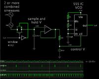
This simulates an analog method to change a VCO's frequency by applying a quasi-random control voltage.


This is just to illustrate a concept.

For instance, I used a 555 timer IC for the VCO, because the simulator provides an example circuit for producing adjustable PWM. The output is squarish waves, however I guess you want sine waves, so a few changes will be necessary of course.
 

I'm assuming 96KHz is chosen because it is a common sampling frequency for audio ADC devices in which case, as a clock it probably should be a square wave. I am a little concerned that if I'm right about it being a clock signal, most ADC's will want a multiple of the sampling rate rather than the sampling rate itself. That isn't a problem with the digital method, in fact it makes it a little simpler but for a VCO, particularly using something like a 555, it would be pushing it's speed to the limit.

FlorianB, can you explain how the 96KHz is used in your project please.

Brian.
 

Hmmm... I believe that the world clock is the sample rate (see the product "Apogee Big Bend") but yes, maybe I'm wrong...

All right, here is the idea :

I am an orchestral composer (florianbador.com) and I can't afford an orchestra (about $10K per hour of recording session...)
So I use only soundbanks and I make my best to push the realism as far as possible (see "Solemn Lullaby" on my website)

There is a big problem with strings, it's that when real violinists play a tune, their note is not perfect, even a digital recording of them would sound almost like a tape recording (randomly slightly detuned)
But with soundbanks, the violinists that played each note of the bank focused too much on making the notes perfect, and it doesn't sound natural in the end.

So what I usually do, is apply a custom pitch bend graph on each string recordings in order to detune them (once in the box).
The problem is that it is absurd to depitch a recording, which results in a sort of resampling and thus, a loss of quality, while the same thing (even better) could be done when playing these samples with the soundcard, using an irregular playback sample rate.
That way, not only that it would save a lot of time (just have to adjust a few buttons and the "random tape effect" would apply in real time) but it would also improve the quality (no resample needed)

Ideally, I would have a little box with 2-3 buttons and a BNC output going to the soundcard of my orchestral banks.
The 2-3 buttons would be something like :
- maximum pitch amplitude (even though it is random)
- average speed of variation (although it would be multiple sine waves combined as BradTheRad said)
- (eventually if I could switch to other rates than 96KHz it would be nice too)

You can probably better understand why irregular impulses would be a disaster... If products like Apogee Big Bend are sold $1500, there's a reason. Jitter effect would be terrible on violins.
So the trick is to have a random clock on the large scale (100-1000ms), but still extremely stable on the short scale (in a 20ms period) It is like a very smoothed graph in the end.
 
Last edited:

I tried listening to the "Solemn Lullaby" but my internet is so slow I get one second of music followed by about 5 seconds of buffering. The one second bursts sound good though but are not really long enough to hear the effect.

I think you may have to revisit the thinking behind this. From what I'm understanding, you have high quality samples taken at 96KHz rate and you want to detune the source that creates that rate so the samples are slightly faster or slower. If you are recording at 96KHz rate it means you 'snapshot' a point on the sound waveform 96,000 times a second and if you are playing a sample back it means you are creating a waveform from 96,000 snapshotted (is that a word?) points per second to rebuild the wave shape. In both cases, the electronics needs to perform many operations per sample to read, store or retrieve the sample information and hence runs very much faster. It may be the clock that needs the adjustment is much faster than 96KHz, for example, most audio DACs made by Crystal Semiconductors work at 12.288MHz. In itself, that isn't a problem, it is still easy to sythesize that frequency and ones very close to it but you may have to break into the electronics to access the point where the clock is actually used.

Brian.
 

From what I know, pro audio soundcards have a buffer of audio data (samples) that we usually adjust via software, and this creates a little delay (usually around 10ms or less for the best soundcards)
And when a soundcard isn't fast enough to render all samples (w/ multitracks e.g.) we hear clicks, so we increase the buffer size. That is usually how we configure a soundcard.

From that, I guess we can conclude that the soundcard / DA converter waits for the clock to release a prepared sample from the buffer.

Also, wikipidia says "it clocks each sample".
https://en.wikipedia.org/wiki/Word_clock

I'm pretty sure each impulse is a sample release, as simple as that.
Also, the Apogee Big Bend would talk about it somewhere if that wasn't the case I guess.

PS: for Solemn Lullaby you can let it play silently in the background until the whole video is loaded so you can press play again after.
 

Here is a confirmation that a world clock signal IS running at the audio sample rate (96KHz in my case usually)
I don't know the tension but I guess it's 5v.

**broken link removed**

In the first paragraph named "THEORY" :
It locks in fractions of a second to the input signal, follows even extreme varipitch changes with phase accuracy, and locks directly within a range of 28 kHz up to 200 kHz.

So they don't only say that the converter will lock to the input frequency, but it will also allow varipitch (what I want) while cleaning up jitter!
This is almost a paradox, it's what I meant when I said that it has to vary at a large scale, but still be very stable if we zoom closer.

Now, they also give us an idea of unit : less than 5ns of jitter should be the target.
On 96KHz, it is about 0.05%.

HAPPY NEW YEAR :)
 
Last edited:

The name is WORD clock not WORLD clock! No wonder I'm confused (it doesn't take much to confuse me). It's the metronome tick that sets the rate that samples are taken.

Firstly, I should point out that the oscilloscope traces they show are pretty meaningless, they show the traces synchronized to their own system on channel 2 so I would expect it to look clean. If instead they had triggered on channel 1, the original signal would look stable and theirs would appear to have jitter. It does however show that differences occur between them. From what I can see, their product is a PLL which locks to incoming data and produces it's own 'clean' signal as a replacement. It's purpose would be more for eliminating tone slippage between samples from different sources by locking them all to a clock derived from another source. It states if follows varipitch signals, not produce them, this is normal in a PLL. In video talk we would call it 'gen-lock', where one camera is used to bring the others into sync to allow clean wipes/fades between pictures.

At 96KHz, 5nS is about 0.0005% variance by the way.

Happy New Year!

Brian.
 

Status
Not open for further replies.

Part and Inventory Search

Welcome to EDABoard.com

Sponsor

Back
Top