Continue to Site

Welcome to EDAboard.com

Welcome to our site! EDAboard.com is an international Electronics Discussion Forum focused on EDA software, circuits, schematics, books, theory, papers, asic, pld, 8051, DSP, Network, RF, Analog Design, PCB, Service Manuals... and a whole lot more! To participate you need to register. Registration is free. Click here to register now.

How to make a circuit to drive 6 red LED with the below flashing pattern on 12/24VDC?

Status
Not open for further replies.

me_guitarist

Full Member level 6
Joined
Oct 3, 2006
Messages
338
Helped
0
Reputation
0
Reaction score
0
Trophy points
16
Location
Malaysia
Activity points
0
How to make a circuit to drive 6 red LED with the below flashing pattern on 12/24VDC?

1/2 second on, 1/2 second off, 1/2 second on, 1/2 second off, 1/2 second on, 1/2 second off, 1 second off then repeat next cycle. The circuit must accept multiple synchronization pattern from other module.

yr help will be much appreciated.

RGDS,
 

pic led strobe

Anybody know how to do a multi flashing pattern LED circuit?
 

led strobe 555 timer

Maybe program an eight pin PIC (if accurate timing is essential) or a six pin PIC (if approx timing will do) to output that sequence, and step up the power using a darlington?

In the first case, you will need a Vreg chip, a darlington, a crystal and the programmed PIC.

In the second case, the crystal can be omitted.

Since there is only one output needed, the other pins can be programmed to be inputs and used for sychronizing.

This can be hard to do without a programmed microcontroller: the chip count is going to go way up.
 

pic chip led strobe

Hi neelandan,

Thanks for yr advice.
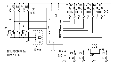
How can I make this circuit work in 24VDC with required flash pattern & synchronization?

79_1212981678.gif


and how to do the programing?

Thanks in advance!
 

strobo led schematic

In the circuit you have provided, IC2 (voltage regulator) has the function of absorbing the difference between the supply input voltage (12) and the regulated output voltage (5) and dissipating it as heat.

You can look for a linear voltage regulator which will accept the 24 volts you intend to apply and output the required 5 volts. It will have to waste a large amount of the applied power as heat and so is going to get hot.

If that is of concern to you, you might look for an smps which accepts 24 volts and outputs 5 volts. Try searching for ' "roman black" smps two transistor '

You will need a PIC programmer and associated software to program the PIC. Designs abound on the net.

If you post details about the end application of this circuit, I might be able to help you better.
 

power led strobe projects

Hi Neelanda,

The application will be a 24VDC 6 LEDs strobe with synchronize function, the synchronize source will be variety pattern with supply on/off controlling. But I guess if the circuit flashed itself with standard flashing pattern, the optional synchronization will interrupt the standard flash pattern.

Am I right?
 

led double strobe circuit

Hi,
If you want all the six LEDs to be driven from a single fuctuating pattern, then you can use a simple shift register loaded with a ' 00010101' pattern and rotate right with a half sec. clock. Take the 8th output and drive the LEDs using a transistor. If you use CMOS shift register, you can use 12V supply directly. I do not know if it will help you.

Regards,
Laktronics
 

Re: LED Strobe

Some parameters haven't yet been told: intended LED current, methode for the said synchronisation. I would also prefer a newer PIC type as 16F688 with internal oscillator compared to classical 16F84.
 

LED Strobe

LED current: 20mA
Rated Voltage: 24VDC

The standard flashing pattern:
1/2sec on,1/2sec off,1/2sec on, 1/2sec off, 1/2sec on, 1/2sec off, 1sec off, next cycle.

Synchronization: user selectable from sync module to overwrite the standard flash pattern.
 

Re: LED Strobe

Do you intend an optical or electrical synchronization? If so, how about the signal strength and quality of received signal?

What's the purpose of individual LEDs? Or can they be series connected, dricen by the same signal?
 

LED Strobe

The LEDs are series connected & driven by same signal, intended for electrical synchronization.
 

Re: LED Strobe

Then a timer, a 3 bit binary counter and some decoding logic would also do.
Decoding logic in VHDL notation:
Code:
LED <= NOT q(0) AND (NOT q(1) OR   NOT q(2));
But a microprocessor (could be 8 pin type) would give minimum part count anyway.
The output stage can be a single npn transistor connected as current source.
 

LED Strobe

how to make the circuit work on 24VDC without creating heat
 

Re: LED Strobe

Series connecting the LEDs reduces the total current consumption to only little more than LED current. That's still 0.5 W total, but the LED voltage drop is already around 10 V. For 5 V processor supply, use an NPN transistor with 220 ohms emitter resistor as current source, connecting the base to IO pin, series connected LEDs at the collector with 24 V supply. A 78L05 can supply the processor.
 

LED Strobe

What do u mean IO pin?

Can this circuit use a PIC10F204 MCU as well? How?
As I only need 1 flash pattern so try to get the cheapest MCU.
 

Re: LED Strobe

You can use any microprocessor to my opinion. It actually needs one output pin to drive the LED output stage and one input pin for the sync signal. We ususally call the pins used for input or output IO.

But it doesn't matter, which uP I would use, cause you have to program it.
 

LED Strobe

thanks FvM.

I'll try to post my schematic here & pls help to make it work.

Added after 5 minutes:

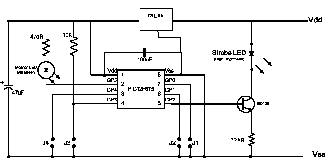
I'm thinking of using this circuit.
http://picprojects.org.uk/projects/images/Ledstrobe.png

The monitoring LED will be omitted & increase the STROBE LED to 8pcs. input 20~28VDC, with three pulse, will this work?how about the 5V for PIC?
 

Re: LED Strobe

I already suggested a partly different circuit:

20_1214691536.gif
 

LED Strobe

Thanks Fvm.

The 7805 is too large for my circuit.
Can I replace it with a z5v ener diode across Vss & Vdd?
or...

Stil searching for easiest circuit, a 555 timer will do this job? I need three pulse: 1/2s on 1/2s off, 1/2s on, 1/2s off, 1/2s on 1/2s off, 1 s off, next cycle.
 

Status
Not open for further replies.

Part and Inventory Search

Welcome to EDABoard.com

Sponsor

Back
Top